
System cable bundle - r + r
- Make
- Fiat
- Model
- Stilo Factory Service Manual
- Year
- 2001–2007
- Section
- Petrol injection system › System cable bundle - r + r
System cable bundle - r + r
Removing
Place the car on the ramp.
- 1016A10 sound-proofing cover - r + r
- 5530B56 BATTERY DRIP TRAY COVER - R.R.
Disconnect the battery negative terminal.
| Name | Connector | |
|---|---|---|
| Battery | A1 |
- 7055B54 under-engine guard - r r
1. Undo the nuts (1a) and move the cable protection (1a).
2. Disconnect the electrical connection for the rpm sensor.
| Name | Connector | |
|---|---|---|
| 2 | RPM sensor | K46 |
3. Disconnect the electrical connection for the detonation sensor.
| Name | Connector | |
|---|---|---|
| 3 | Detonation sensor | K50 |
4. Disconnect the electrical connection from the engine oil pressure warning light switch.
| Name | Connector | |
|---|---|---|
| 4 | Engine oil pressure sensor (switch) | K30 |
5. Disconnect the electrical connections from the starter motor.
| Name | Connector | |
|---|---|---|
| 5 | Starter motor | A20 |
6. Disconnect the electrical connections from the alternator.
| Name | Connector | |
|---|---|---|
| 6 | Alternator | A10 |
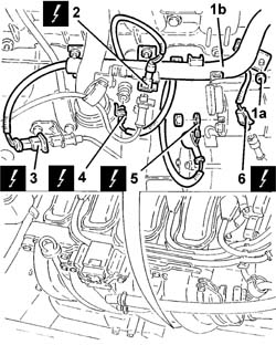
- 1048A32 sleeve from air cleaner to intake manifold - r + r
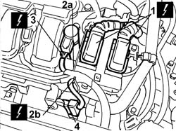
1. Disconnect the electrical connections for the engine management control unit.
| Name | Connector | |
|---|---|---|
| 1 | Engine management ECU | M10 |
2. Undo the fixing bolt (2a) and disconnect the control unit earth lead (2b).
| Name | Connector | |
|---|---|---|
| 2 | Injection ECU earth | C60 |
3. Disconnect the electrical connections from the ignition coils.
| Name | Connector | |
|---|---|---|
| 3 | Injector | N70 |
4. Disconnect the electrical connections from the injectors.
| Name | Connector | |
|---|---|---|
| 4 | Injector junction | D81 |
Disconnect the earths on the cylinder head extensions.
| Name | Connector | |
|---|---|---|
| Earth on engine | C40 |
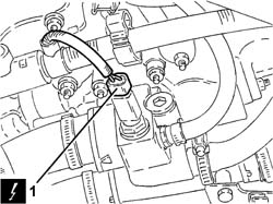
1. Disconnect the electrical connection from the engine coolant temperature sensor.
| Name | Connector | |
|---|---|---|
| 1 | Engine temperature sender unit | K36 |
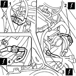
1. Disconnect the electrical connection for the rear Lambda sensor for the catalytic preconverter.
| Name | Connector | |
|---|---|---|
| 1 | Lambda sensor on pre-catalyzer | K15 |
2. Disconnect the electrical connection for the front Lambda sensor for the catalytic preconverter.
| Name | Connector | |
|---|---|---|
| 2 | Lambda sensor on pre-catalyzer -2 | K16 |
3. Disconnect the electrical connection for the throttle body.
| Name | Connector | |
|---|---|---|
| 3 | Integrated throttle body actuator | N75 |
4. Disconnect the electrical connection for the reversing sensor.
| Name | Connector | |
|---|---|---|
| 4 | Reversing lights switch | I20 |
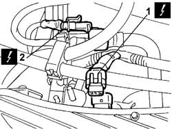
1. Disconnect the electrical connection from the intake air temperature/pressure sensor.
| Name | Connector | |
|---|---|---|
| 1 | Integrated air temperature sensor | K43 |
2. Disconnect the electrical connection from the fuel vapour recovery solenoid.
| Name | Connector | |
|---|---|---|
| 2 | Fuel vapour recovery solenoid | L10 |
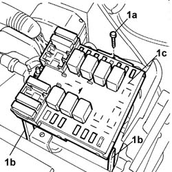
1. Unscrew the bolt (1a), undo retainers (1b) and and move the engine bay junction unit (1c).
1. Disconnect the electrical connection from the engine bay control unit coupling.
| Name | Connector | |
|---|---|---|
| 1 | Engine compartment junction unit | B1 |
2. Disconnect the facia wiring harness connection coupling electrical connection.
| Name | Connector | |
|---|---|---|
| 2 | Engine coupling/ i.e. | D24 |
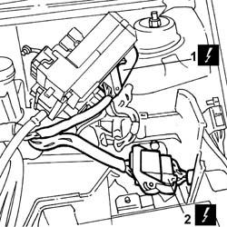
Release the wiring from the retaining collars and remove it.
Refitting
Place the cable loom back in its housing and fix it using the bands.
Connect the facia/engine wiring harness connection coupling electrical connection.
| Name | Connector | |
|---|---|---|
| Engine coupling/ i.e. | D24 |
Connect the electrical connection to the engine bay control unit coupling.
| Name | Connector | |
|---|---|---|
| Engine compartment junction unit | B1 |
Fit the engine bay junction unit in the retainers and tighten the retaining bolt.
Connect the electrical connection to the fuel vapour recovery solenoid.
| Name | Connector | |
|---|---|---|
| Fuel vapour recovery solenoid | L10 |
Connect the electrical connection to the intake air temperature/pressure sensor.
| Name | Connector | |
|---|---|---|
| Integrated air temperature sensor | K43 |
Connect the reversing sensor electrical connection.
| Name | Connector | |
|---|---|---|
| Reversing lights switch | I20 |
Connect the electrical connection of the throttle body.
| Name | Connector | |
|---|---|---|
| Integrated throttle body actuator | N75 |
Connect the electrical connection for the front Lambda sensor for the catalytic preconverter.
| Name | Connector | |
|---|---|---|
| Lambda sensor on pre-catalyzer -2 | K16 |
Connect the electrical connection for the rear Lambda sensor to the preconverter.
| Name | Connector | |
|---|---|---|
| Lambda sensor on pre-catalyzer | K15 |
Connect the electrical connection to the engine coolant temperature sensor.
| Name | Connector | |
|---|---|---|
| Engine temperature sender unit | K36 |
Connect the earths to the cylinder head extensions
| Name | Connector | |
|---|---|---|
| Earth on engine | C40 |
Connect the electrical connections to the injectors.
| Name | Connector | |
|---|---|---|
| Injector junction | D81 |
Connect the electrical connections to the ignition coils.
| Name | Connector | |
|---|---|---|
| Injector | N70 |
Fit the earth to the engine control unit and tighten the bolt.
| Name | Connector | |
|---|---|---|
| Injection ECU earth | C60 |
Connect the engine control unit electrical connections
| Name | Connector | |
|---|---|---|
| Engine management ECU | M10 |
- 1048A32 sleeve from air cleaner to intake manifold - r + r
Connect the electrical connection to the alternator.
| Name | Connector | |
|---|---|---|
| Alternator | A10 |
Connect the electrical connection to the starter motor.
| Name | Connector | |
|---|---|---|
| Starter motor | A20 |
Connect the electrical connection to the engine oil pressure warning light switch.
| Name | Connector | |
|---|---|---|
| Engine oil pressure sensor (switch) | K30 |
Connect the electrical connection for the detonation sensor.
| Name | Connector | |
|---|---|---|
| Detonation sensor | K50 |
Connect the electrical connection for the rpm sensor.
| Name | Connector | |
|---|---|---|
| RPM sensor | K46 |
Position the wiring duct protection and fix it using the bolts.
- 7055B54 under-engine guard - r r
Connect the battery negative terminal.
| Name | Connector | |
|---|---|---|
| Battery | A1 |
- 5530B56 BATTERY DRIP TRAY COVER - R.R.
- 1016A10 sound-proofing cover - r + r
Remove the car from the ramps.
Parts & tools for this job For 2001 Fiat Stilo
- PARTEngine gasket setSearch: Fiat Stilo 2001 engine gasket set
- TOOLTorque wrenchSearch: 3/8 inch torque wrench
- TOOLFeeler gauge setSearch: feeler gauge set
Links open Amazon search results in a new tab. As an Amazon Associate I earn from qualifying purchases.