
Control switches resistor unit
- Make
- Land Rover
- Model
- Defender 90 Workshop Manual (NAS)
- Section
- Repair › Control switches resistor unit
Air conditioningControl switches resistor unit
CONTROL SWITCHES RESISTOR UNIT
Service repair no - 82.20.10 - Temperature Control Service repair no - 82.20.26 Switch Service repair no - 82.20.11 - Fan Switch Remove
Remove
- Remove fascia duct bezel. See fascia duct bezel
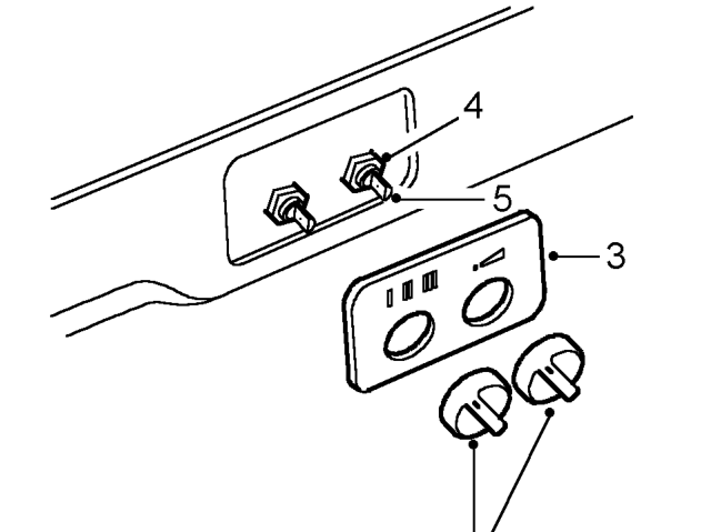
- Pull control knobs from switches.
- Remove switch panel.
- Remove nut securing switch to bezel.
- Remove switch.
NOTE: Fan switch to left.
Refit
- Fit temperature control switch. Position capillary tube inside duct to RH side.
- Fit and tighten nut securing switch to bezel.
- Fit switch panel.
Refit
- Fit control knobs.
- Fit fascia duct bezel. See fascia duct bezel; Refit
- Carry out system test. See Adjustment, System test
- Carry out system test.
NOTE: Access below evaporator unit.
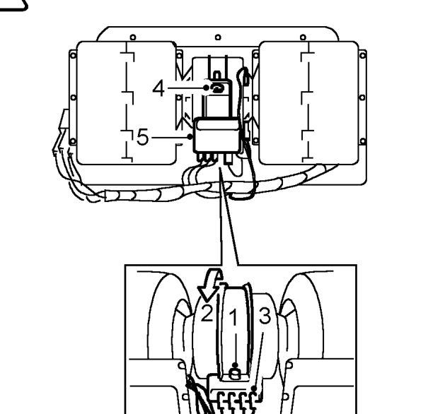
- Loosen outer screw securing resistor unit to clamp.
- Rotate resistor on motor.
- Disconnect Lucars from resistor unit.
NOTE: Resistor wires: G, U, R and O
- Remove screws securing resistor to clamp.
- Remove resistor unit and clamp.
- Position clamp over motor and place resistor, terminals downward, onto motor.
- Fit screws and tighten inner screw only.
- Fit Lucars to resistor unit, in correct sequence.
- Rotate resistor to fitted position and tighten outer screw. See Adjustment, System test
Parts & tools for this job For Land Rover Defender
- TOOLA/C manifold gauge setSearch: AC manifold gauge set
- TOOLUV leak detection kitSearch: AC UV leak detection kit
- PARTCabin filterSearch: Land Rover Defender cabin filter
Links open Amazon search results in a new tab. As an Amazon Associate I earn from qualifying purchases.