
See Adjustment, System test
- Make
- Land Rover
- Model
- Defender 90 Workshop Manual (NAS)
- Section
- Repair › See Adjustment, System test
Air conditioningSee Adjustment, System test
Refit
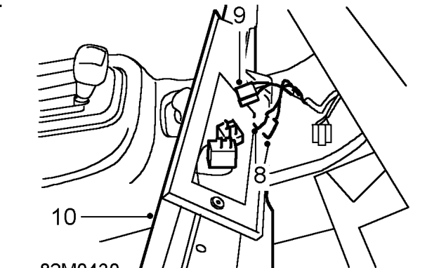
- Position bezel assembly and connect multiplug
- Connect Lucars to temperature control switch.
- Position capillary tube to RH side of bezel.
- Fit screws securing cover to rear of bezel.
- Connect multiplug to fan interlock relay.
- Position bezel assembly and insert capillary tube
- Fit bezel assembly to panel and above
- Fit cold air vents.
- Carry out system test.
- Disconnect 2 Lucars from temperature control switch.
- Disconnect multiplug from fan switch.
- Remove bezel assembly.
Do not carry out further dismantling if component is removed for access only.
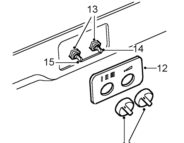
- Pull control knobs from switches.
- Remove switch panel.
- Remove nuts securing switches to bezel.
- Remove temperature control switch.
- Remove fan switch.
- Transfer components to new panel.
to fan switch.
60 mm, 2.5 in into evaporator fins
evaporator casing, secure with screws.
See Adjustment, System test
Parts & tools for this job For Land Rover Defender
- TOOLA/C manifold gauge setSearch: AC manifold gauge set
- TOOLUV leak detection kitSearch: AC UV leak detection kit
- PARTCabin filterSearch: Land Rover Defender cabin filter
Links open Amazon search results in a new tab. As an Amazon Associate I earn from qualifying purchases.