
Brakes (Hydraulic System): Description and operation
- Make
- Land Rover
- Model
- Freelander System Description and Operation (UK)
- Section
- Description and operation › Hydraulic System
Hydraulic System
The hydraulic unit of the modulator consists of a pump, 12 solenoid operated valves and accumulator and damper chambers. Each brake unit has its own inlet and outlet valves.
The hydraulic system operates the brakes in response to brake pedal movement.
For normal brake operation, brake pedal movement is assisted by the brake servo assembly and transmitted to the master cylinder assembly. The master cylinder assembly converts brake pedal movement to hydraulic pressure. Primary and secondary brake pipe circuits supply the hydraulic pressure to the brakes: the primary circuit supplies the front left and rear right brakes; the secondary circuit supplies the front right and rear left brakes.
A red, brake warning lamp in the instrument pack illuminates if the fluid level in the hydraulic system falls to an unsafe level. The brake fluid level is checked via a level switch in the brake fluid reservoir.
On right hand drive vehicles the brake fluid reservoir is remotely located on a bracket on the bulkhead. Left hand drive vehicles have the brake fluid reserver in the usual position on top of the master cylinder.
Vacuum for the brake servo assembly is obtained from the engine inlet manifold (petrol models) or a vacuum pump (diesel models) through a vacuum line and non return valve.
To reduce operating noise, sleeving is installed on some of the brake pipes in the engine compartment and the pipes are located in sprung pipe clips.
ABS Hydraulic System Schematic
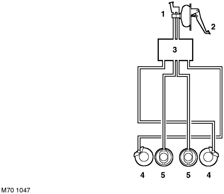
1 Servo/Master cylinder assembly 2 Brake pedal 3 ABS modulator
4 Front brake 5 Rear brake
Brake Servo Assembly
The brake servo assembly provides power assistance to reduce the pedal load when braking.
The assembly is attached to the front of the pedal box and comprises a circular housing containing a diaphragm, push rods, valve and filter. A push rod at the rear of the housing is connected to the brake pedal. The vacuum line is connected to a port in the front face of the housing.
With the brake pedal released and the engine running, vacuum pressure is present on both sides of the diaphragm. When the brake pedal is pressed, the rear push rod moves forward and opens the valve to allow atmospheric pressure through the filter into the pedal side of the diaphragm. The pressure differential acting on the diaphragm increases the pressure being applied by the brake pedal, which is transmitted to the master cylinder via the forward push rod.
If the servo fails, the hydraulic system will still function but will require greater pedal effort due to the lack of vacuum assistance.
Parts & tools for this job For Land Rover Freelander
- PARTBrake padsSearch: Land Rover Freelander brake pads
- TOOLBrake bleeder kitSearch: one man brake bleeder kit
- FLUIDBrake fluidSearch: brake fluid
Links open Amazon search results in a new tab. As an Amazon Associate I earn from qualifying purchases.