
Inlet manifold chamber gasket - ’K8’ (page 2 of 2)
- Make
- Rover
- Model
- 200 Workshop Manual
- Year
- 1995–1999
- Section
- Repairs
Manifold & exhaust systemsInlet manifold chamber gasket - ’K8’ · page 2 of 2
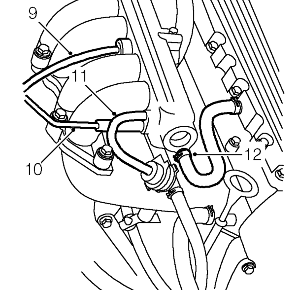
- Depress plastic collar and disconnect brake servo vacuum hose from manifold chamber.
- Disconnect ECM vacuum hose from manifold chamber.
- Disconnect fuel pressure regulator vacuum hose from manifold chamber.
- Release clip and disconnect breather from manifold chamber.
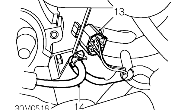
- Release injector harness multiplug from mounting bracket beneath throttle housing.
- Release coil h.t. lead from mounting bracket beneath throttle housing.
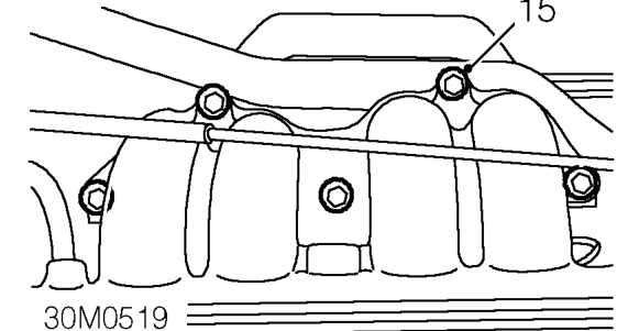
- Remove 5 bolts securing manifold chamber to inlet manifold.
- Remove inlet manifold chamber.
- Remove and discard inlet manifold chamber gasket.
Refit
- Clean mating surfaces of inlet manifold and manifold chamber gasket.
- Position new gasket to inlet manifold.
- Fit manifold chamber to inlet manifold and align.
- Fit bolts securing manifold chamber to inlet manifold and tighten progressively to 25 Nm.
- Secure coil h.t. lead and injector harness multiplug to mounting bracket beneath throttle housing.
- Connect breather hose to manifold chamber and secure with clip.
- Connect fuel pressure regulator vacuum hose to manifold chamber.
- Connect ECM vacuum hose to manifold chamber.
- Connect brake servo vacuum hose to manifold chamber.
- Connect throttle cable to throttle cam.
- Locate throttle cable adjusting nut in abutment bracket.
- Connect purge hose to manifold chamber and secure with clip.
- Connect breather hose to throttle housing and secure with clip.
- Connect multiplug to IACV.
- Connect multiplug to TP sensor.
- Connect air intake hose to throttle housing and secure with clip.
- Connect battery earth lead.
- Adjust throttle cable. See ENGINE MANAGEMENT SYSTEM - MEMS, Adjustments.
Parts & tools for this job For 1995 Rover 200
- PARTExhaust gasketSearch: Rover 200 1995 exhaust gasket
- TOOLPenetrating oilSearch: penetrating oil
- TOOLOBD2 scannerSearch: OBD2 scanner
Links open Amazon search results in a new tab. As an Amazon Associate I earn from qualifying purchases.