
Steering column assembly (page 3 of 3)
- Make
- Rover
- Model
- 400 Workshop Manual
- Year
- 1995–2000
- Section
- Repairs
SteeringSteering column assembly · page 3 of 3
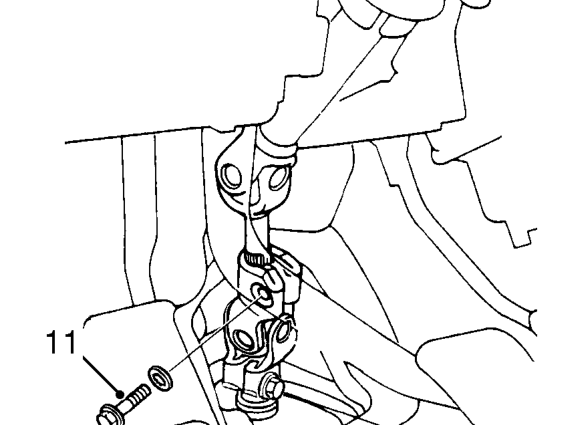
- Remove bolt securing universal joint to column.
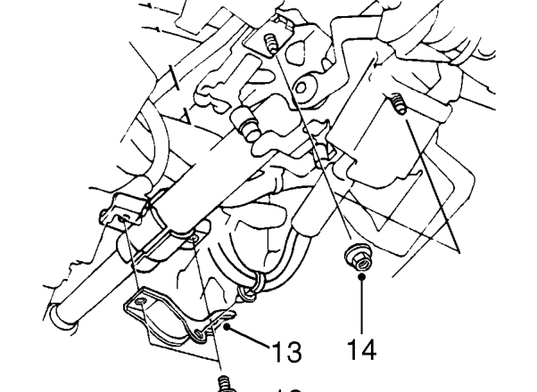
- Remove 2 bolts securing lower column clamp to pivot bracket.
- Remove clamp.
- Remove 2 flange nuts securing column upper bracket.
- Remove column assembly. Do not carry out further dismantling if component is removed for access only.
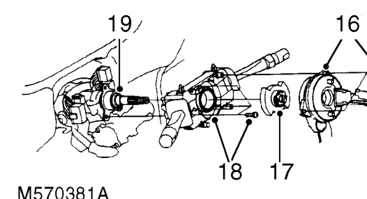
- Remove 3 screws and withdraw rotary coupler. Ensure coupler is taped securely.
- Remove indicator cancel cam
- Remove 3 screws and withdraw column switch assembly.
- Remove steering lock. See this section.
Refit
- Fit steering lock and tighten shear bolts fully.
- Fit column switch assembly.
- Fit indicator cancel cam, set engagement tangs horizontal.
- Fit rotary coupler.
- Position column assembly, engage universal joint splines aligning the bolt hole with the flat on the shaft and fit bolt securing column to universal joint, DO NOT tighten.
- Raise column and engage top bracket on studs and fit nuts, DO NOT tighten.
- Fit lower clamp, tighten bolts to 22 Nm.
- Tighten top bracket nuts to 16 Nm .
- Tighten universal joint bolt to 28 Nm.
- Position joint cover and retain with stud and clips.
- Connect starter switch multiplugs.
- Connect combined lighting and wiper switch multiplugs.
- 97.5MY on: Connect multiplug to passive coil.
- ’D’ series: Connect SRS rotary coupler to SRS main harness. Retain connector
- Fit column upper and lower covers.
- Fit lower cover and driver’s pocket.
- Fit steering wheel. See this section.
- Fit driver’s airbag module. See RESTRAINT SYSTEMS, Repairs.
Parts & tools for this job For 1995 Rover 400
- TOOLTie rod end toolSearch: tie rod end puller
- TOOLBall joint separatorSearch: ball joint separator
- FLUIDPower steering fluidSearch: Rover power steering fluid
Links open Amazon search results in a new tab. As an Amazon Associate I earn from qualifying purchases.