
Abs high pressure system - bleed
- Make
- Rover
- Model
- 600 Rover 600 Repair Manual - Volumes 1 and 2 - 2nd Edition
- Section
- Brakes - ABS: repairs › Abs high pressure system - bleed
Brakes and ABSAbs high pressure system - bleed
ABS HIGH PRESSURE SYSTEM - BLEED
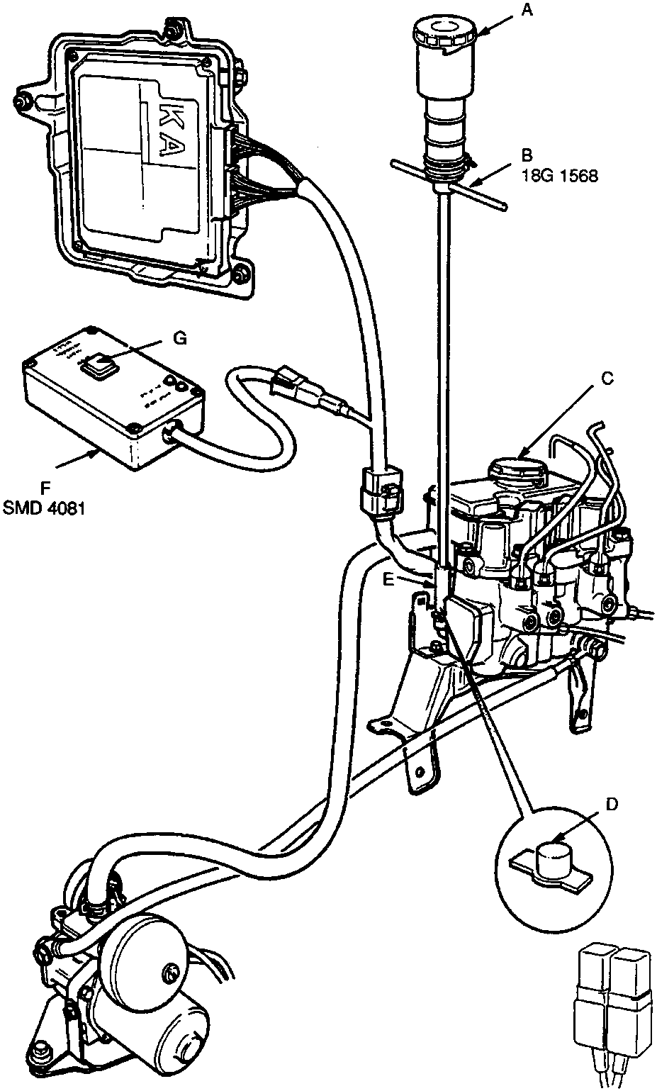
- Filler cap
- 'T' Wrench reservoir
- Pump reservoir
- Bleed screw cap
- 'T' Wrench tool
- Bleed control unit
- 'START CYCLE' button
Parts & tools for this job For Rover 600
- TOOLBrake bleeder kitSearch: one man brake bleeder kit
- FLUIDBrake fluidSearch: brake fluid
- TOOLBrake line flaring toolSearch: brake line flaring tool
Links open Amazon search results in a new tab. As an Amazon Associate I earn from qualifying purchases.