
ABS Control Unit Replacement
- Make
- Rover
- Model
- 600 Rover 600 Repair Manual - Volumes 1 and 2 - 2nd Edition
- Section
- Brakes - ABS: repairs › ABS Control Unit Replacement
Brakes and ABSABS Control Unit Replacement
ABS Control Unit Replacement
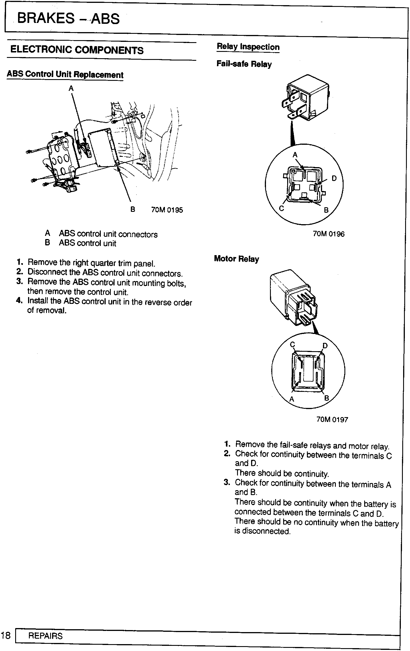
A ABS control unit connectors
B ABS control unit
- Remove the right quarter trim panel.
- Disconnect the ABS control unit connectors.
- Remove the ABS control unit mounting bolts, then remove the control unit.
- Install the ABS control unit in the reverse order of removal.
Relay Inspection
Fail-safe Relay
Motor Relay
- Remove the fail-safe relays and motor relay.
- Check for continuity between the terminals C and D.
There should be continuity. - Check for continuity between the terminals A and B.
There should be continuity when the battery is connected between the terminals C and D. There should be no continuity when the battery is disconnected.
Parts & tools for this job For Rover 600
- TOOLOBD2 scanner with ABSSearch: OBD2 scanner ABS SRS
- TOOLDigital multimeterSearch: automotive digital multimeter
Links open Amazon search results in a new tab. As an Amazon Associate I earn from qualifying purchases.