
Removal/Installation
- Make
- Rover
- Model
- 600 Rover 600 Repair Manual - Volumes 1 and 2 - 2nd Edition
- Section
- Brakes - ABS: repairs › Removal/Installation
Brakes and ABSRemoval/Installation
Removal/Installation
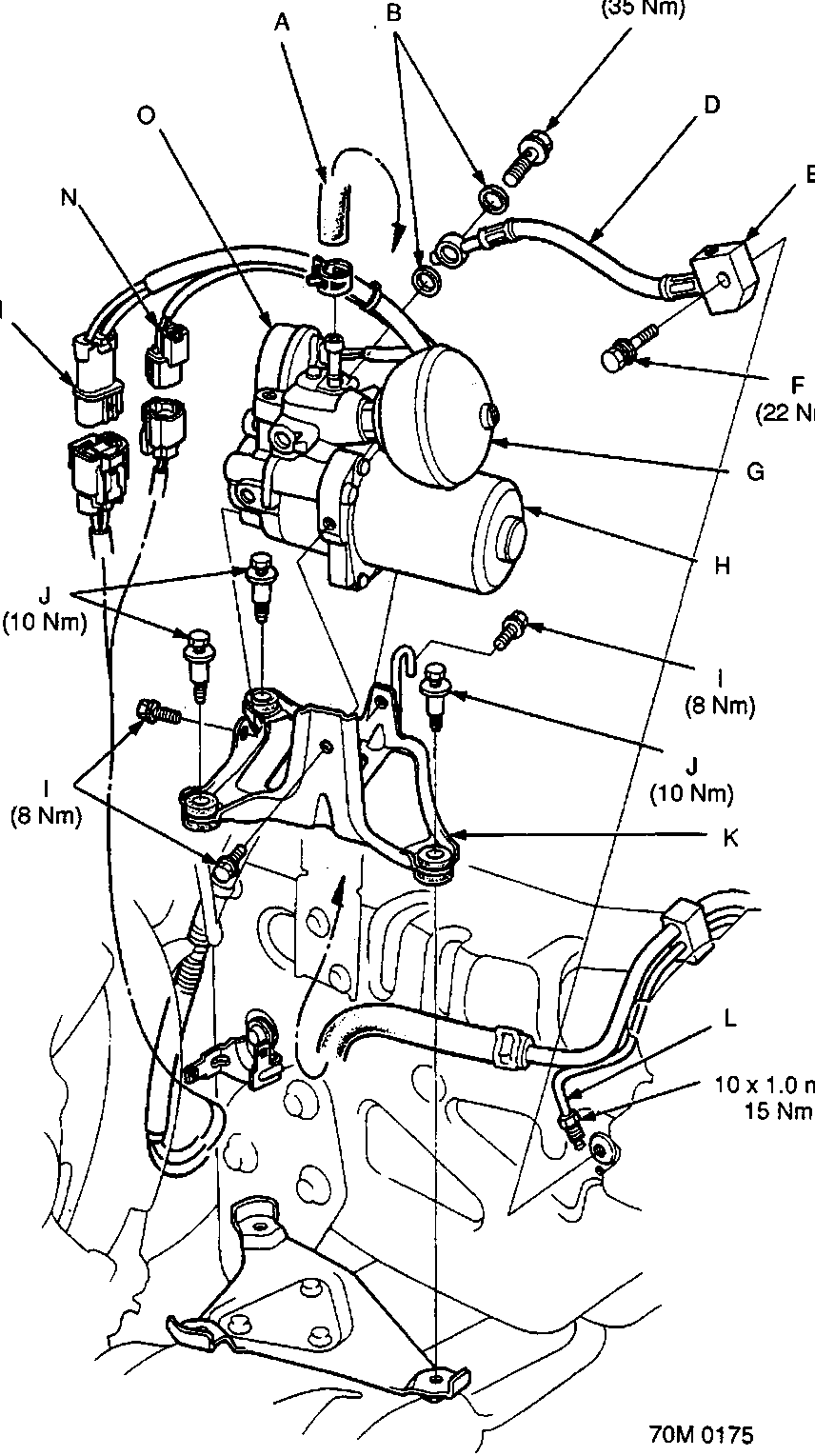
- A Brake hose
- B Sealing washers
- C Banjo bolt
- D High-pressure hose
- E Pressure hose joint
- F 8 mm bolt
- G Accumulator
- H ABS Pump assembly
- I 6 mm bolts
- J Mounting bolts
- K ABS Pump assembly bracket
- L High-pressure pipe
- M Motor connector
- N Pressure switch connector
- O Pressure switch
Parts & tools for this job For Rover 600
- TOOLOBD2 scanner with ABSSearch: OBD2 scanner ABS SRS
- TOOLDigital multimeterSearch: automotive digital multimeter
Links open Amazon search results in a new tab. As an Amazon Associate I earn from qualifying purchases.