
Caution:
- Make
- Rover
- Model
- 600 Rover 600 Repair Manual - Volumes 1 and 2 - 2nd Edition
- Section
- Brakes - ABS: repairs › Caution:
Brakes and ABSCaution:
Note: If the primary piston assembly is difficult to remove, apply compressed air from the primary piston side port.
CAUTION:
- Do not use high pressure air or bring the nozzle too close to the port.
- Place a suitable piece of cloth over the master cylinder to collect the primary piston when it is ejected.
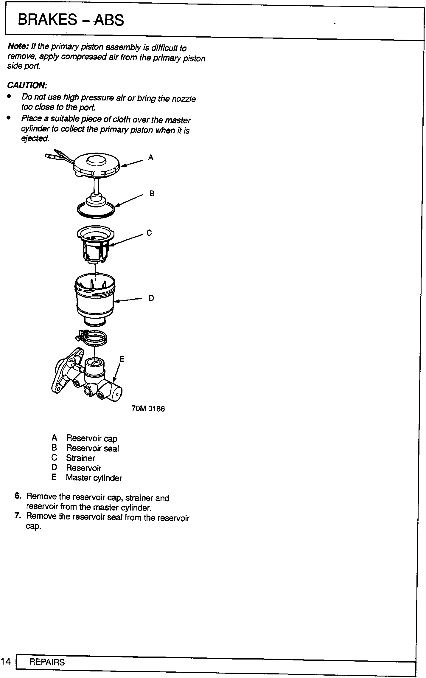
- A Reservoir cap
- B Reservoir seal
- C Strainer
- D Reservoir
- E Master cylinder
- Remove the reservoir cap, strainer and reservoir from the master cylinder.
- Remove the reservoir seal from the reservoir cap.
Parts & tools for this job For Rover 600
- TOOLOBD2 scanner with ABSSearch: OBD2 scanner ABS SRS
- TOOLDigital multimeterSearch: automotive digital multimeter
Links open Amazon search results in a new tab. As an Amazon Associate I earn from qualifying purchases.