
Front
- Make
- Rover
- Model
- 600 Rover 600 Repair Manual - Volumes 1 and 2 - 2nd Edition
- Section
- Brakes - ABS: repairs › Front
Brakes and ABSFront
Front
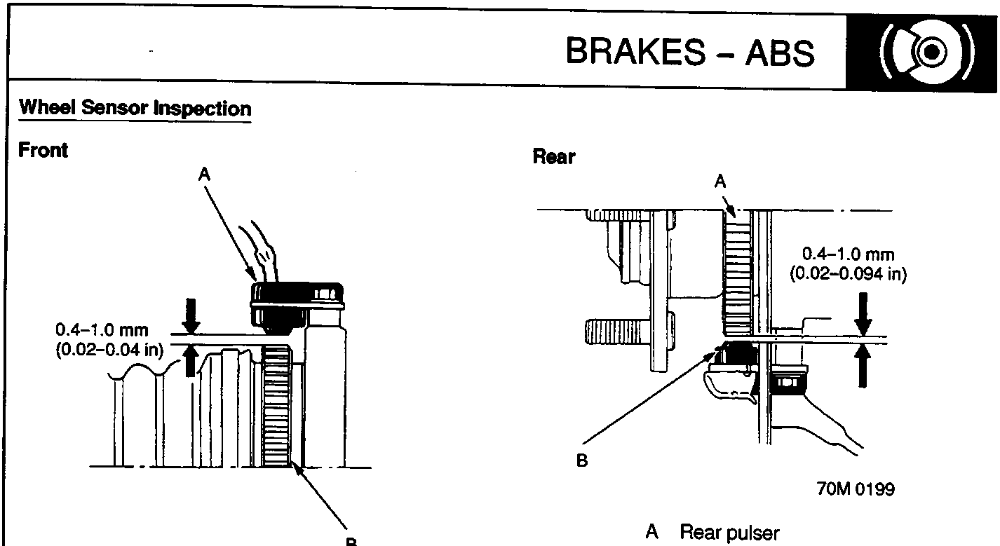
A Front wheel sensor
B Front pulser
- Check the front pulser for chipped or damaged teeth.
- Measure the air gap between the wheel sensor and pulser all the way around while rotating the driveshaft by hand.
Standard: 0.4–0.1 mm (0.02–0.04 in)
Note: If the gap exceeds 1.0 mm (0.04 in), the probability is a distorted knuckle which should be replaced.
Rear
A Rear pulser
B Rear wheel sensor
- Check the rear pulser for chipped or damaged teeth.
- Measure the air gap between the wheel sensor and pulser all the way around while rotating the hub bearing unit by hand.
Standard: 0.4–0.1 mm (0.02–0.04 in)
Note: If the gap exceeds 1.0 mm (0.04 in), the probability is a distorted knuckle which should be replaced.
Parts & tools for this job For Rover 600
- TOOLOBD2 scanner with ABSSearch: OBD2 scanner ABS SRS
- TOOLDigital multimeterSearch: automotive digital multimeter
Links open Amazon search results in a new tab. As an Amazon Associate I earn from qualifying purchases.