
Reassembly (page 3 of 3)
- Make
- Rover
- Model
- 600 Rover 600 Repair Manual - Volumes 1 and 2 - 2nd Edition
- Section
- Brakes - ABS: repairs
Brakes and ABSReassembly · page 3 of 3
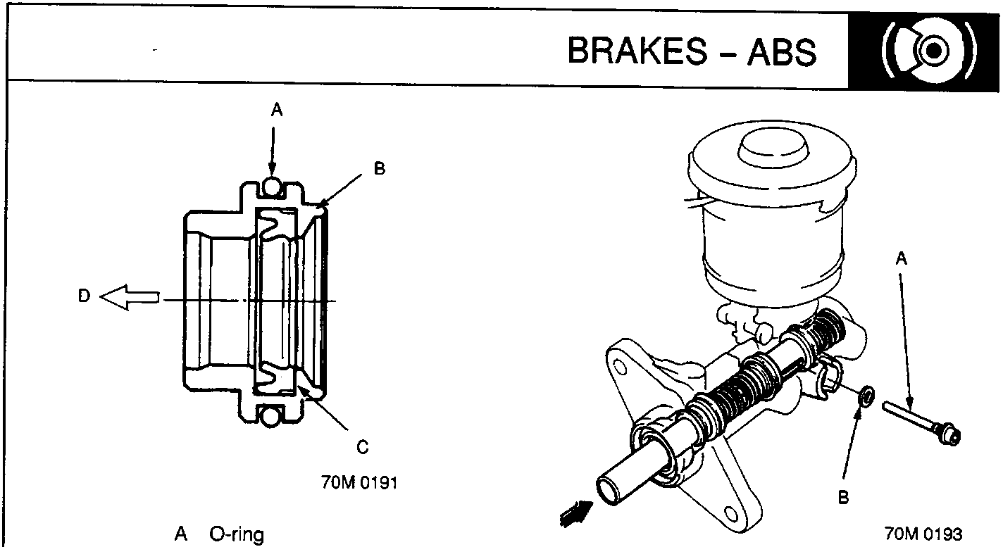
A O-ring
B Piston guide
C Secondary cup
D Front
A Stop bolt
B Sealing washer
- Apply recommended grease in the master cylinder seal set to a new O-ring and the secondary cup in a new piston guide, and install the O-ring onto the piston guide.
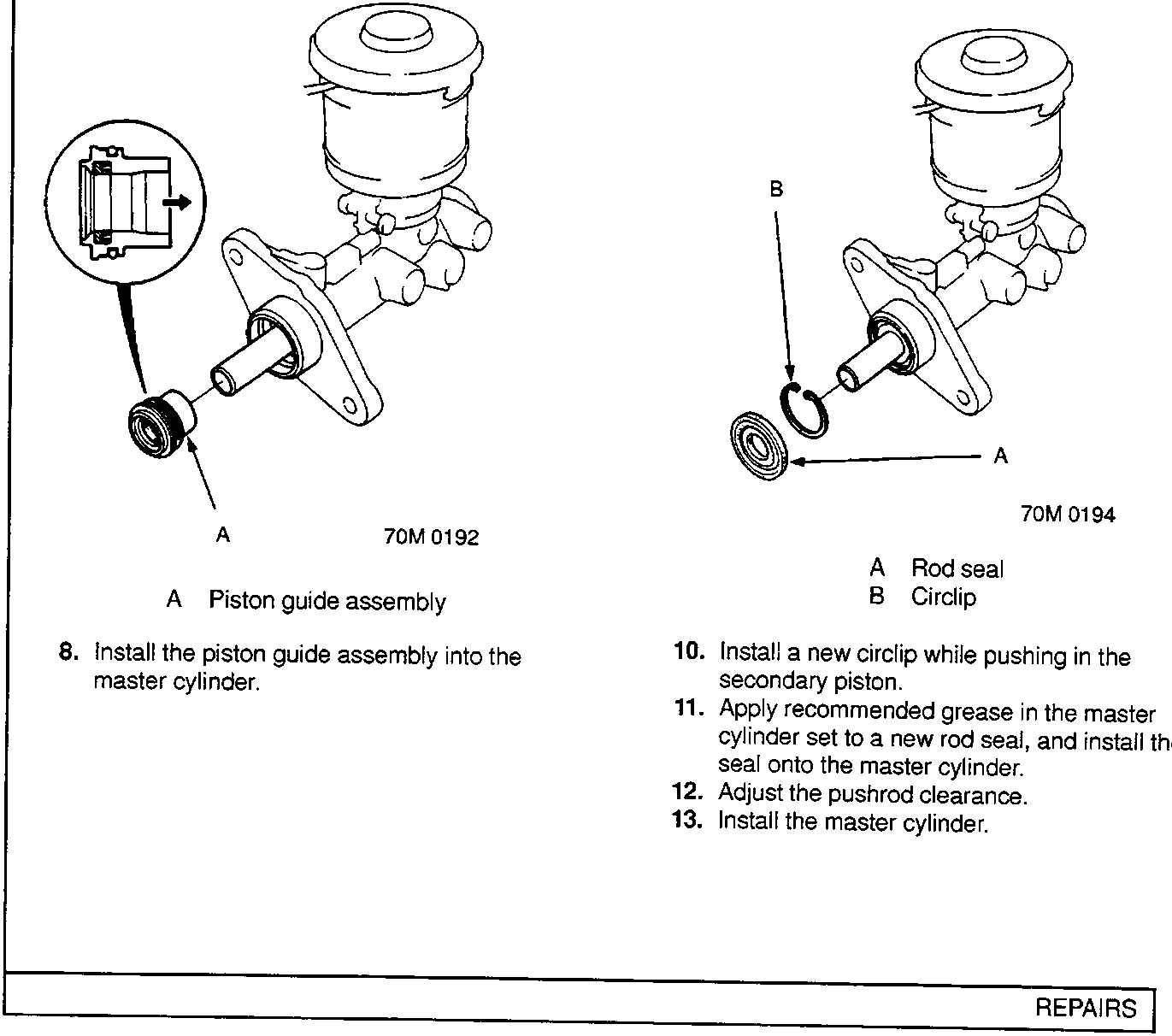
A Piston guide assembly
- Install the piston guide assembly into the master cylinder.
- Align the slot in the primary piston with the stop bolt hole by pushing the secondary piston in, and install the stop bolt with a new sealing washer.
- Install a new circlip while pushing in the secondary piston.
- Apply recommended grease in the master cylinder set to a new rod seal, and install the seal onto the master cylinder.
- Adjust the pushrod clearance.
- Install the master cylinder.
Parts & tools for this job For Rover 600
- TOOLOBD2 scanner with ABSSearch: OBD2 scanner ABS SRS
- TOOLDigital multimeterSearch: automotive digital multimeter
Links open Amazon search results in a new tab. As an Amazon Associate I earn from qualifying purchases.