
Brake Booster
- Make
- Rover
- Model
- 600 Rover 600 Repair Manual - Volumes 1 and 2 - 2nd Edition
- Section
- Brakes: repairs › Brake Booster
Brakes and ABSBrake Booster
Brake Booster
Booster Leak Test
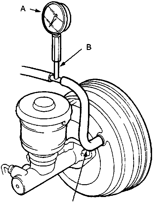
A Vacuum gauge
B Tube joint adaptor
C Vacuum joint tube A
- Install the special tools as shown.
- Start the engine, adjust the engine speed with the accelerator pedal so that the vacuum gauge readings show 300 – 500 mm Hg (11.8 – 19.7 in Hg), then stop the engine.
- Read the vacuum gauge.
If the vacuum reading decreases 20 mmHg (0.8 inHg) or more after 30 seconds, check the following parts for leaks.
- Check valve.
- Vacuum hose, pipe.
- Seals.
- Brake booster.
- Master cylinder.
CAUTION: Do not try to disassemble the brake booster. Replace the brake booster as a complete assembly.
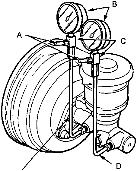
A Bleed valves
B Pressure gauges
C Pressure gauge attachment C
D Pressure gauge joint pipe
E Pressure gauge joint pipe
- Install the vacuum gauge as shown in the leak test.
- Connect the oil pressure gauges to the master cylinder using the attachments as shown.
Note: Item E will vary depending upon whether the car is fitted with ABS, see TOOLS.
- Bleed air through the valves.
- Start the engine.
- Apply a pressure of 200 N (20 kg, 44 lbs) to the brake pedal and, referring to the appropriate table, check that the pressure gauges register the correct pressures at the specified vacuums (as indicated on the vacuum gauge).
Parts & tools for this job For Rover 600
- PARTBrake padsSearch: Rover 600 brake pads
- TOOLBrake bleeder kitSearch: one man brake bleeder kit
- FLUIDBrake fluidSearch: brake fluid
Links open Amazon search results in a new tab. As an Amazon Associate I earn from qualifying purchases.