
Original page
- Make
- Rover
- Model
- 600 Rover 600 Repair Manual - Volumes 1 and 2 - 2nd Edition
- Section
- Brakes: repairs › Original page
Brakes and ABSOriginal page · page 1 of 7
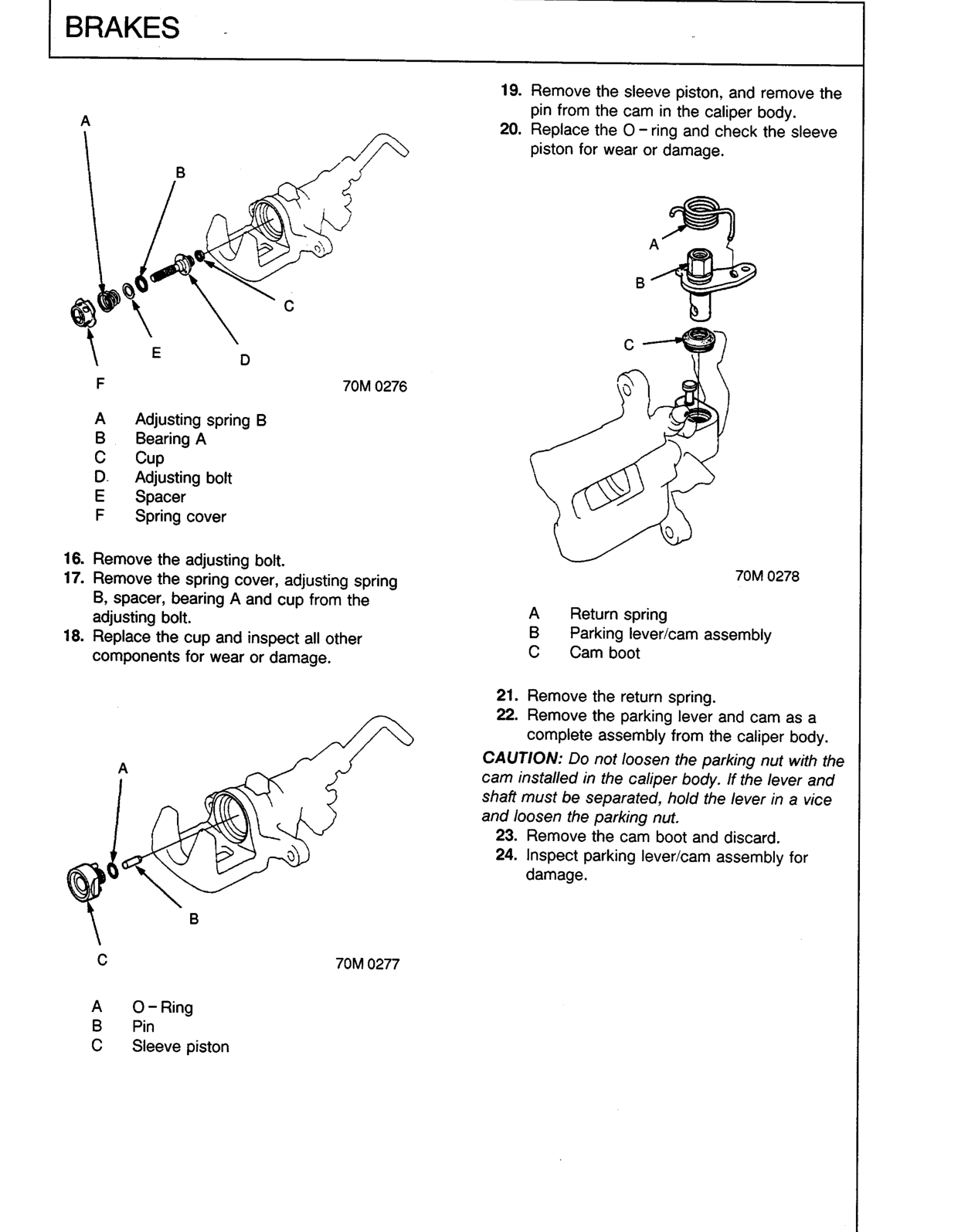
- Remove the adjusting bolt.
- Remove the spring cover, adjusting spring B, spacer, bearing A and cup from the adjusting bolt.
- Replace the cup and inspect all other components for wear or damage.
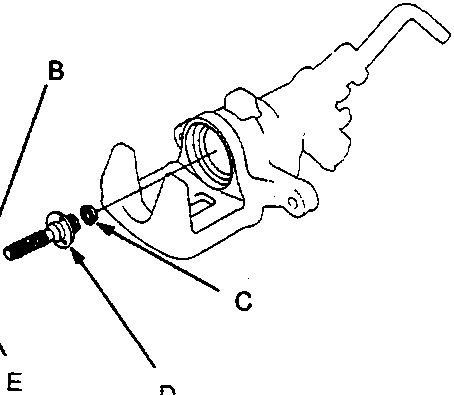
- Adjusting spring B
- Bearing A
- Cup
- Adjusting bolt
- Spacer
- Spring cover
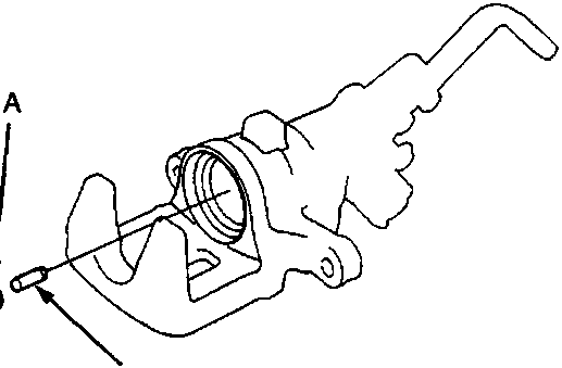
- O-Ring
- Pin
- Sleeve piston
- Remove the sleeve piston, and remove the pin from the cam in the caliper body.
- Replace the O-ring and check the sleeve piston for wear or damage.
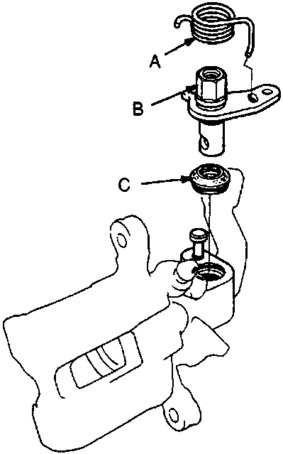
- Return spring
- Parking lever/cam assembly
- Cam boot
- Remove the return spring.
- Remove the parking lever and cam as a complete assembly from the caliper body.
CAUTION: Do not loosen the parking nut with the cam installed in the caliper body. If the lever and shaft must be separated, hold the lever in a vice and loosen the parking nut.
- Remove the cam boot and discard.
- Inspect parking lever/cam assembly for damage.
Original page
Parts & tools for this job For Rover 600
- PARTBrake padsSearch: Rover 600 brake pads
- TOOLBrake bleeder kitSearch: one man brake bleeder kit
- FLUIDBrake fluidSearch: brake fluid
Links open Amazon search results in a new tab. As an Amazon Associate I earn from qualifying purchases.