
Original page (page 2 of 7)
- Make
- Rover
- Model
- 600 Rover 600 Repair Manual - Volumes 1 and 2 - 2nd Edition
- Section
- Brakes: repairs
Brakes and ABSOriginal page · page 2 of 7
GREASE :
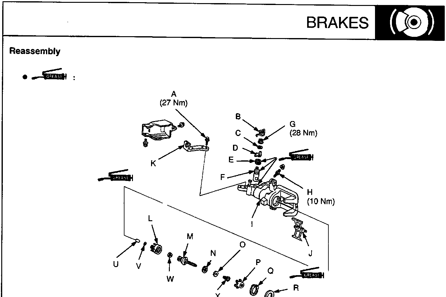
- A 8 mm Flange bolt
- B Return spring
- C Spring washer
- D Lever
- E Cam boot
- F Cam
- G Parking nut
- H Bleed screw
- I Caliper body
- J Pad spring
- K Arm
- L Sleeve piston
- M Adjusting bolt
- N Bearing A
- O Spacer
- P Spring cover
- Q Circlip
- R Piston seal
- S Piston
- T Piston boot
- U Pin
- V O – Ring
- W Cup
- X Adjusting spring B
- Y Inner pad shim
- Z Brake pads
- AA Retainer
- AB Pins
- AC Outer pad shim
- AD Pin boots
- AE Caliper bracket
Parts & tools for this job For Rover 600
- PARTBrake padsSearch: Rover 600 brake pads
- TOOLBrake bleeder kitSearch: one man brake bleeder kit
- FLUIDBrake fluidSearch: brake fluid
Links open Amazon search results in a new tab. As an Amazon Associate I earn from qualifying purchases.