
Original page
- Make
- Rover
- Model
- 600 Rover 600 Repair Manual - Volumes 1 and 2 - 2nd Edition
- Section
- Brakes: repairs › Original page
Brakes and ABSOriginal page · page 1 of 4
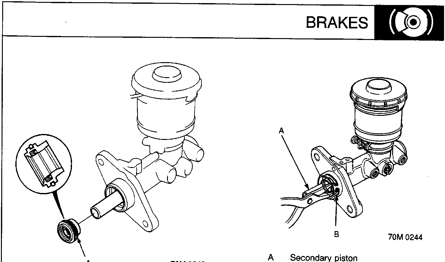
A Piston guide assembly
- Install the piston guide assembly into the master cylinder.
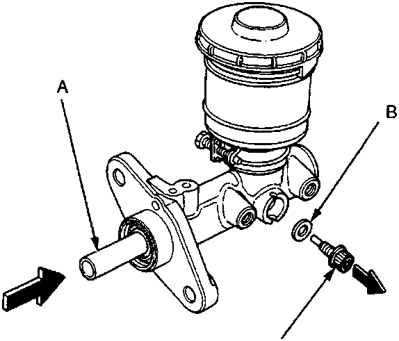
A Secondary piston
B Sealing washer
C Stop bolt
9 Nm
- Install the stop bolt with a new sealing washer while pushing in the secondary piston, and tighten the stop bolt.
A Secondary piston
B Circlip
- Install a new circlip while pushing in the secondary piston.
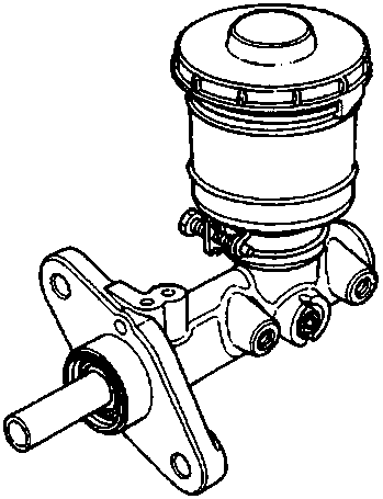
A Rod seal
- Apply recommended grease to the new master cylinder rod seal and install the seal onto the master cylinder.
Original page
Parts & tools for this job For Rover 600
- PARTBrake padsSearch: Rover 600 brake pads
- TOOLBrake bleeder kitSearch: one man brake bleeder kit
- FLUIDBrake fluidSearch: brake fluid
Links open Amazon search results in a new tab. As an Amazon Associate I earn from qualifying purchases.