
Disassembly
- Make
- Rover
- Model
- 600 Rover 600 Repair Manual - Volumes 1 and 2 - 2nd Edition
- Section
- Brakes: repairs › Disassembly
Brakes and ABSDisassembly · page 1 of 3
Disassembly
WARNING: Never use an air hose or dry brush to clean brake assemblies. Use a vacuum cleaner, to avoid breathing brake dust.
Contaminated brake discs or pads reduce stopping ability.
CAUTION: Do not allow brake fluid to come into contact with the paintwork as it will cause surface damage. If brake fluid is spilled on the paintwork, wash it off immediately with water. To prevent spills, cover the hose joints with rags or shop towels.
Clean all parts in brake fluid and air dry; blow out all passages with compressed air.
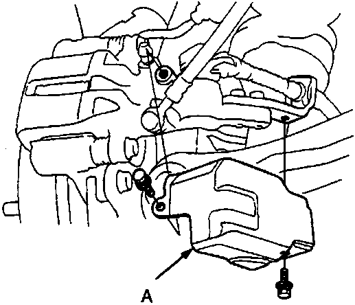
- Caliper shield
- Remove the caliper shield.
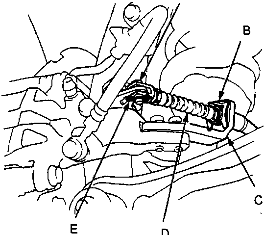
- Clevis pin
- Cable clip
- Arm
- Parking brake cable
- Lock pin
- Remove the lock pin and clevis pin. Replace the lock pin.
Remove the cable clip and disconnect the cable from the arm. Replace the clip.
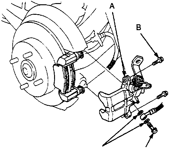
- Caliper bracket
- Caliper mounting bolts
- Banjo bolt
- Sealing washers
- Remove the banjo bolt and two sealing washers. Replace the sealing washers.
- Remove the two caliper mounting bolts and caliper body from the bracket. Check the caliper bracket for cracks or damage.
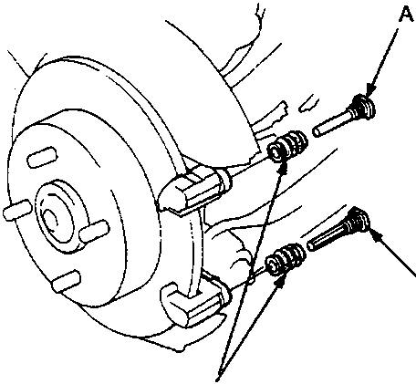
- Pin B
- Pin A
- Pin boots
- Remove the pins and pin boots from the caliper bracket. Replace the pin boots.
Parts & tools for this job For Rover 600
- PARTBrake padsSearch: Rover 600 brake pads
- TOOLBrake bleeder kitSearch: one man brake bleeder kit
- FLUIDBrake fluidSearch: brake fluid
Links open Amazon search results in a new tab. As an Amazon Associate I earn from qualifying purchases.