
Disassembly (page 2 of 3)
- Make
- Rover
- Model
- 600 Rover 600 Repair Manual - Volumes 1 and 2 - 2nd Edition
- Section
- Brakes: repairs
Brakes and ABSDisassembly · page 2 of 3
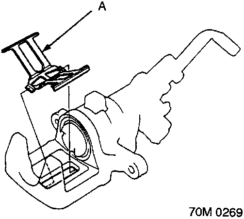
A Pad spring
- Remove the pad spring from the caliper body.
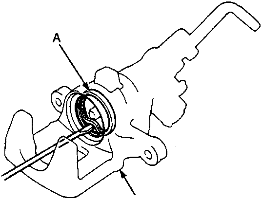
A Piston seal
B Caliper body
- Remove the piston seal and discard.
CAUTION: Take care not to damage the cylinder bore.
- Check the caliper cylinder walls for scoring.
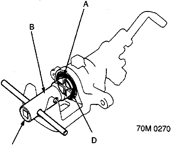
A Piston boot
B Locknut wrench
C Extension bar
D Piston
- Remove the piston by rotating the piston counterclockwise with the special tool and remove the piston boot. Check the piston for scoring.
CAUTION: Avoid damaging the piston.
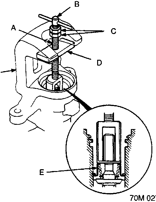
A Brake spring compressor
B Shaft
C Locknuts
D Plate
E Spring cover
F Caliper body
- Install the special tool between the caliper body and spring cover.
CAUTION: Be careful not to damage the inside of the caliper cylinder during caliper disassembly.
Parts & tools for this job For Rover 600
- PARTBrake padsSearch: Rover 600 brake pads
- TOOLBrake bleeder kitSearch: one man brake bleeder kit
- FLUIDBrake fluidSearch: brake fluid
Links open Amazon search results in a new tab. As an Amazon Associate I earn from qualifying purchases.