
Disassembly (page 3 of 3)
- Make
- Rover
- Model
- 600 Rover 600 Repair Manual - Volumes 1 and 2 - 2nd Edition
- Section
- Brakes: repairs
Brakes and ABSDisassembly · page 3 of 3
- Position the locknuts as shown, then turn the shaft until the plate just contacts the caliper body.
Note: Do not compress the spring under the spring cover.
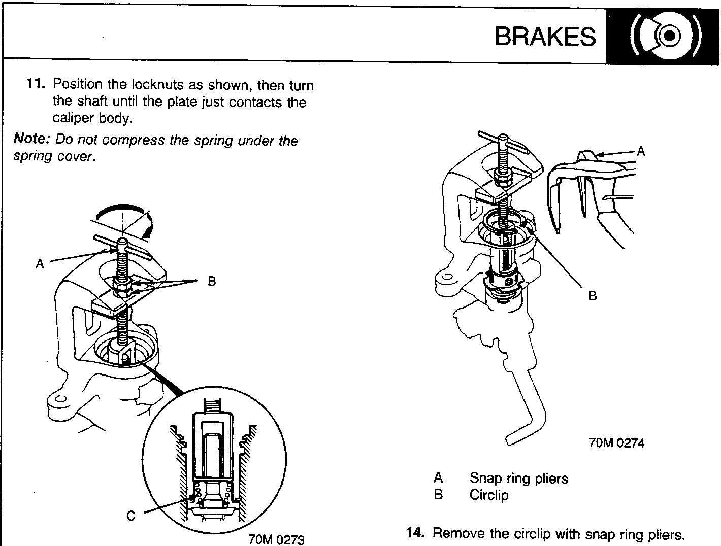
- Turn the shaft clockwise 1/4 – 1/2 turn to compress the adjusting spring B in the caliper body.
CAUTION: To prevent damage to the inner components, do not turn the shaft more than 1/2 turn.
- Lower the locknuts fully and tighten the locknuts securely.
Note: Keep the locknuts in this position until you reinstall the circlip.
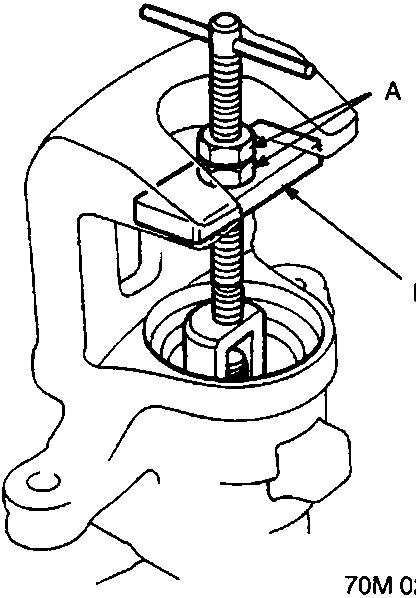
- Hold the plate with your fingers and turn the shaft counterclockwise. Remove the special tool from the caliper.
Parts & tools for this job For Rover 600
- PARTBrake padsSearch: Rover 600 brake pads
- TOOLBrake bleeder kitSearch: one man brake bleeder kit
- FLUIDBrake fluidSearch: brake fluid
Links open Amazon search results in a new tab. As an Amazon Associate I earn from qualifying purchases.