
Original page (page 2 of 4)
- Make
- Rover
- Model
- 600 Rover 600 Repair Manual - Volumes 1 and 2 - 2nd Edition
- Section
- Brakes: repairs
Brakes and ABSOriginal page · page 2 of 4
Note: Master cylinder pushrod – to – piston clearance must be checked and adjustments made, if necessary, before installing master cylinder.
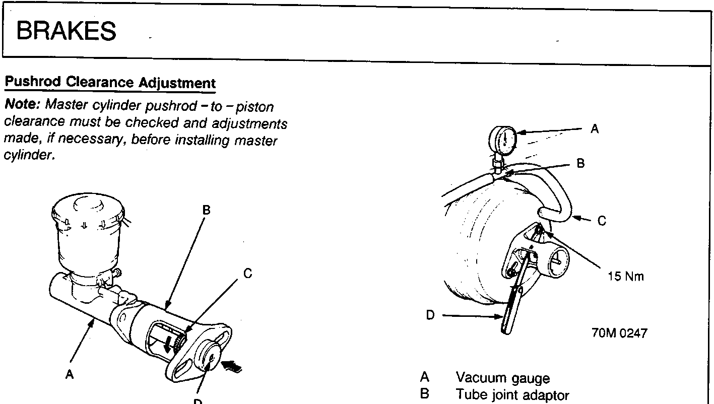
- Master cylinder
- Pushrod adjustment gauge
- Locknut
- Centre shaft
- Vacuum gauge
- Tube joint adaptor
- Vacuum joint tube A
- Feeler gauge
- Set the special tool on the master cylinder body; push in the centre shaft until the top of it contacts with the end of the secondary piston and lock it with locknut.
- Install the special tool upside down on the booster without disturbing the position of the adjusting bolt.
- Install the master cylinder nuts and tighten to the specified torque.
- Fit the special tools as shown and connect to engine vacuum. Maintain an engine speed that will deliver 500mm Hg (20 in Hg) vacuum.
- With a feeler gauge, measure the clearance between the gauge body and the adjusting nut as shown.
Clearance: 0 – 0.4mm (0 – 0.016 in)
Note: If the clearance between the gauge body and the adjusting nut is 0.4mm (0.02 in), the pushrod – to – piston clearance is 0mm. However, if the clearance between the gauge body and adjusting nut is 0mm, the pushrod – to – piston clearance is 0.4mm (0.02 in) or more. Therefore it must be adjusted and rechecked.
Parts & tools for this job For Rover 600
- PARTBrake padsSearch: Rover 600 brake pads
- TOOLBrake bleeder kitSearch: one man brake bleeder kit
- FLUIDBrake fluidSearch: brake fluid
Links open Amazon search results in a new tab. As an Amazon Associate I earn from qualifying purchases.