
Disassembly (page 2 of 2)
- Make
- Rover
- Model
- 600 Rover 600 Repair Manual - Volumes 1 and 2 - 2nd Edition
- Section
- Brakes: repairs
Brakes and ABSDisassembly · page 2 of 2
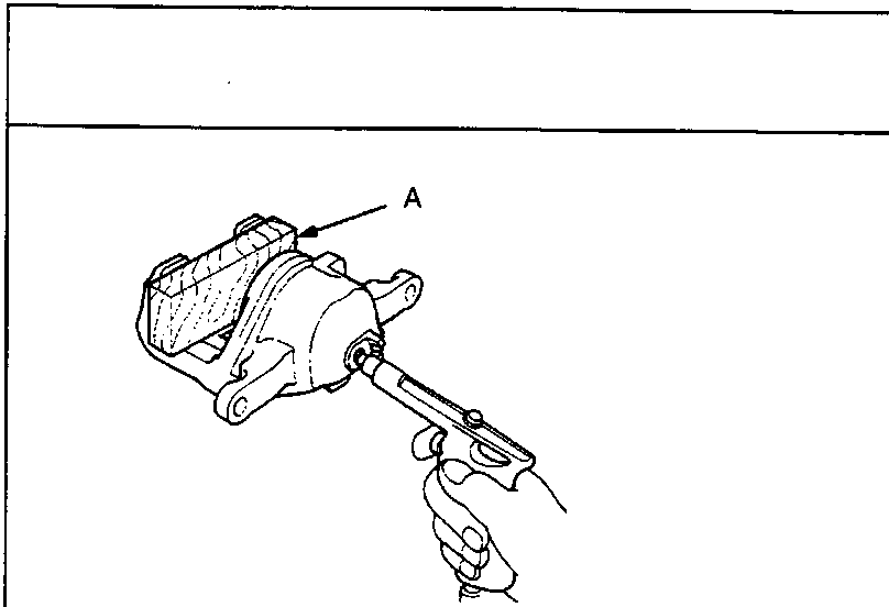
70M 0225
- If necessary, apply compressed air to the caliper fluid inlet to force the piston out. Place a cloth or wooden block as shown to cushion the piston when it is expelled. Use low pressure air in short spurts.
WARNING: Do not place your fingers in front of the piston. Do not use high air pressure.
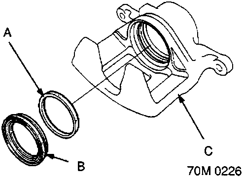
70M 0226
- A Piston seal
- B Piston boot
- C Caliper body
- Remove the piston from the caliper and check the piston for scoring on surface. Check the caliper body for scoring on the cylinder wall.
- Remove the piston boot and piston seal. Replace piston seal and boot.
CAUTION: Take care not to damage the cylinder bore.
Parts & tools for this job For Rover 600
- PARTBrake padsSearch: Rover 600 brake pads
- TOOLBrake bleeder kitSearch: one man brake bleeder kit
- FLUIDBrake fluidSearch: brake fluid
Links open Amazon search results in a new tab. As an Amazon Associate I earn from qualifying purchases.