
Air conditioning signal (page 2 of 3)
- Make
- Rover
- Model
- 600 Rover 600 Repair Manual - Volumes 1 and 2 - 2nd Edition
- Section
- Information
Engine management system – PGM-FiAir conditioning signal · page 2 of 3
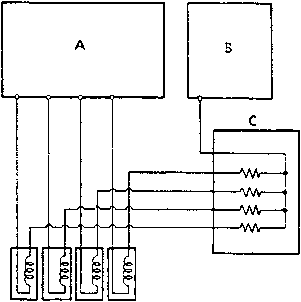
- A ECM
- B PGM – Fi main relay
- C Injector resistor
- D Fuel injectors
The injector resistor lowers the current supplied to the fuel injectors to prevent damage to the fuel injector coils. This allows a faster response time of the fuel injectors.
Parts & tools for this job For Rover 600
- TOOLA/C manifold gauge setSearch: AC manifold gauge set
- TOOLUV leak detection kitSearch: AC UV leak detection kit
- PARTCabin filterSearch: Rover 600 cabin filter
Links open Amazon search results in a new tab. As an Amazon Associate I earn from qualifying purchases.