
Air conditioning signal (page 3 of 3)
- Make
- Rover
- Model
- 600 Rover 600 Repair Manual - Volumes 1 and 2 - 2nd Edition
- Section
- Information
Engine management system – PGM-FiAir conditioning signal · page 3 of 3
CLOSED:
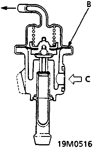
- A Intake manifold vacuum
- B Diaphragm
- C Fuel inlet
OPEN:
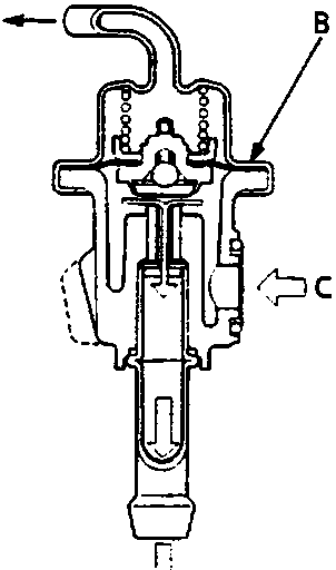
- A Intake manifold vacuum
- B Diaphragm
- C Fuel inlet
- D Fuel return
The fuel pressure regulator maintains a constant fuel pressure to the fuel injectors. When the difference between the fuel pressure and the manifold pressure exceeds 300 kPa the diaphragm is pushed upward, and the excess fuel is fed back into the the fuel tank through the return line.
Parts & tools for this job For Rover 600
- TOOLA/C manifold gauge setSearch: AC manifold gauge set
- TOOLUV leak detection kitSearch: AC UV leak detection kit
- PARTCabin filterSearch: Rover 600 cabin filter
Links open Amazon search results in a new tab. As an Amazon Associate I earn from qualifying purchases.