
Adjustment
- Make
- Rover
- Model
- 600 Rover 600 Repair Manual - Volumes 1 and 2 - 2nd Edition
- Section
- Repairs › Adjustment
Heating and ventilationAdjustment
Adjustment
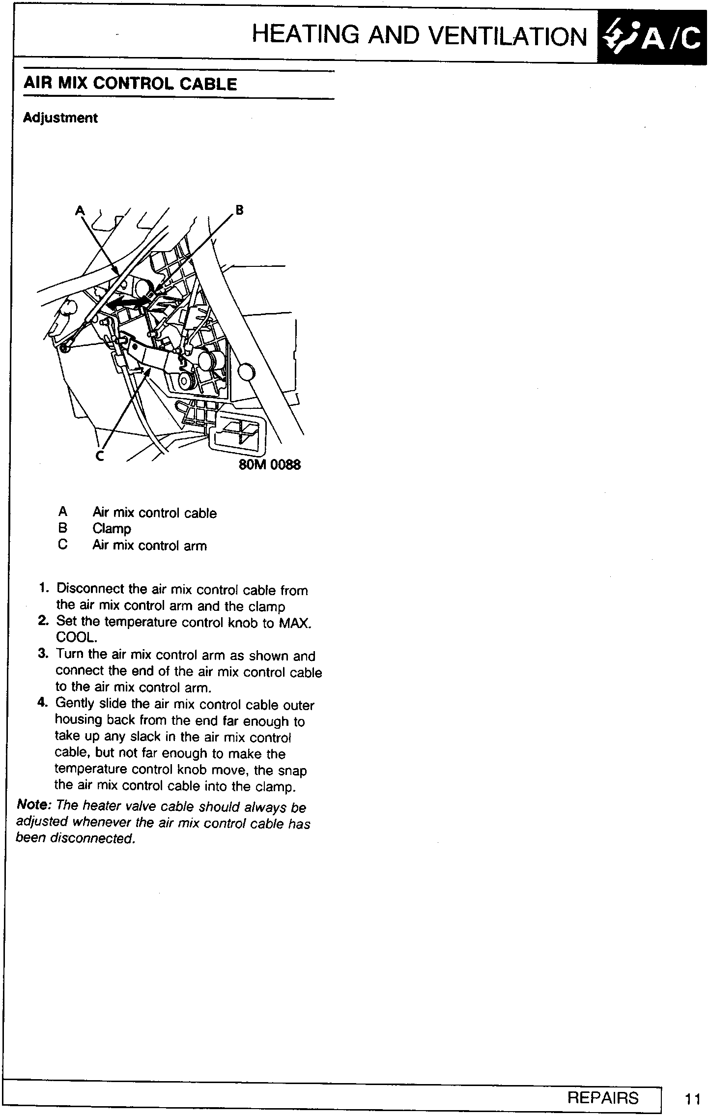
- Air mix control cable
- Clamp
- Air mix control arm
- Disconnect the air mix control cable from the air mix control arm and the clamp
- Set the temperature control knob to MAX. COOL.
- Turn the air mix control arm as shown and connect the end of the air mix control cable to the air mix control arm.
- Gently slide the air mix control cable outer housing back from the end far enough to take up any slack in the air mix control cable, but not far enough to make the temperature control knob move, the snap the air mix control cable into the clamp.
Note: The heater valve cable should always be adjusted whenever the air mix control cable has been disconnected.
Parts & tools for this job For Rover 600
- TOOLA/C manifold gauge setSearch: AC manifold gauge set
- TOOLUV leak detection kitSearch: AC UV leak detection kit
- PARTCabin filterSearch: Rover 600 cabin filter
Links open Amazon search results in a new tab. As an Amazon Associate I earn from qualifying purchases.