
Replacement
- Make
- Rover
- Model
- 600 Rover 600 Repair Manual - Volumes 1 and 2 - 2nd Edition
- Section
- Repairs › Replacement
Heating and ventilationReplacement · page 1 of 2
Replacement
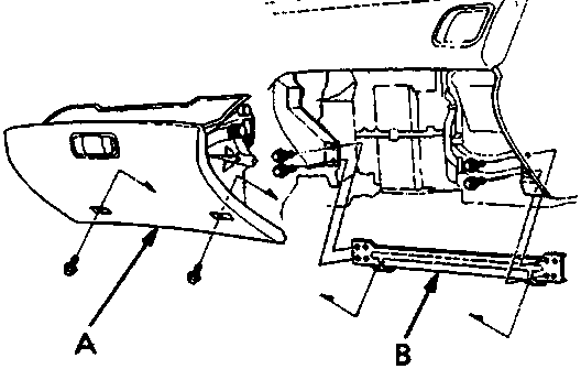
A Glove box
B Glove box frame
- Remove the two screws and the glove box.
- Remove the four screws and the glove box frame.
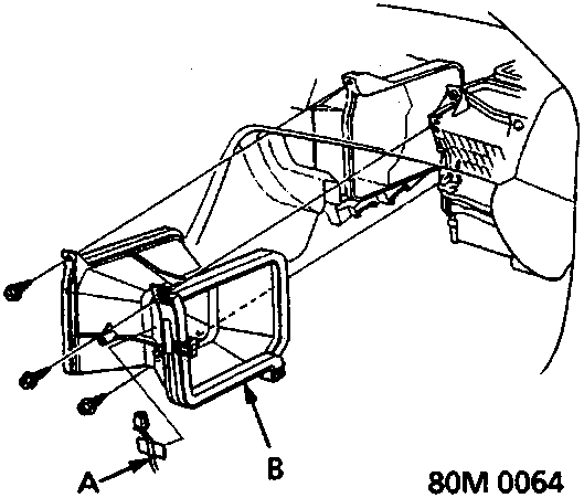
A A/C Thermostat harness connector
B Heater duct
- Remove the A/C thermostat harness connector attached to the heater duct with tape. The remove the three self – tapping screws and the heater duct.
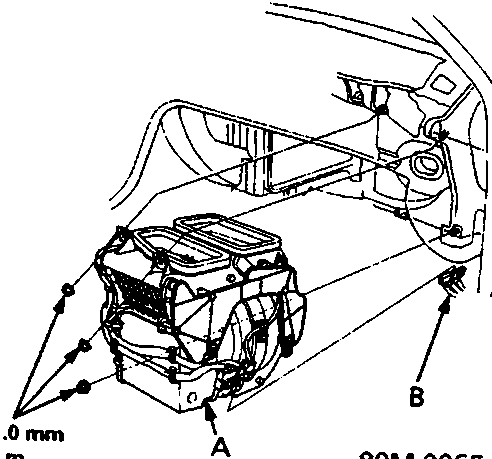
A Blower unit
B Connectors
- Remove the three nuts, then disconnect the three remaining connectors and remove the blower unit.
Parts & tools for this job For Rover 600
- TOOLA/C manifold gauge setSearch: AC manifold gauge set
- TOOLUV leak detection kitSearch: AC UV leak detection kit
- PARTCabin filterSearch: Rover 600 cabin filter
Links open Amazon search results in a new tab. As an Amazon Associate I earn from qualifying purchases.