
Overhaul
- Make
- Rover
- Model
- 600 Rover 600 Repair Manual - Volumes 1 and 2 - 2nd Edition
- Section
- Repairs › Overhaul
Heating and ventilationOverhaul
● Tighten the bleed bolt when all trapped air has escaped and engine coolant begins to flow.
● connect all cables and make sure they are adjusted correctly .
Overhaul
- Remove the four screws and the inlet air duct.
- Remove the four screws and the duct.
- Remove the two screws and the heater core cover.
- Remove the screw and clamp.
- Pull out the heater core
Note: Be careful not to bend the inlet and outlet pipes during heater core removal.
- Assemble in the reverse order of disassembly.
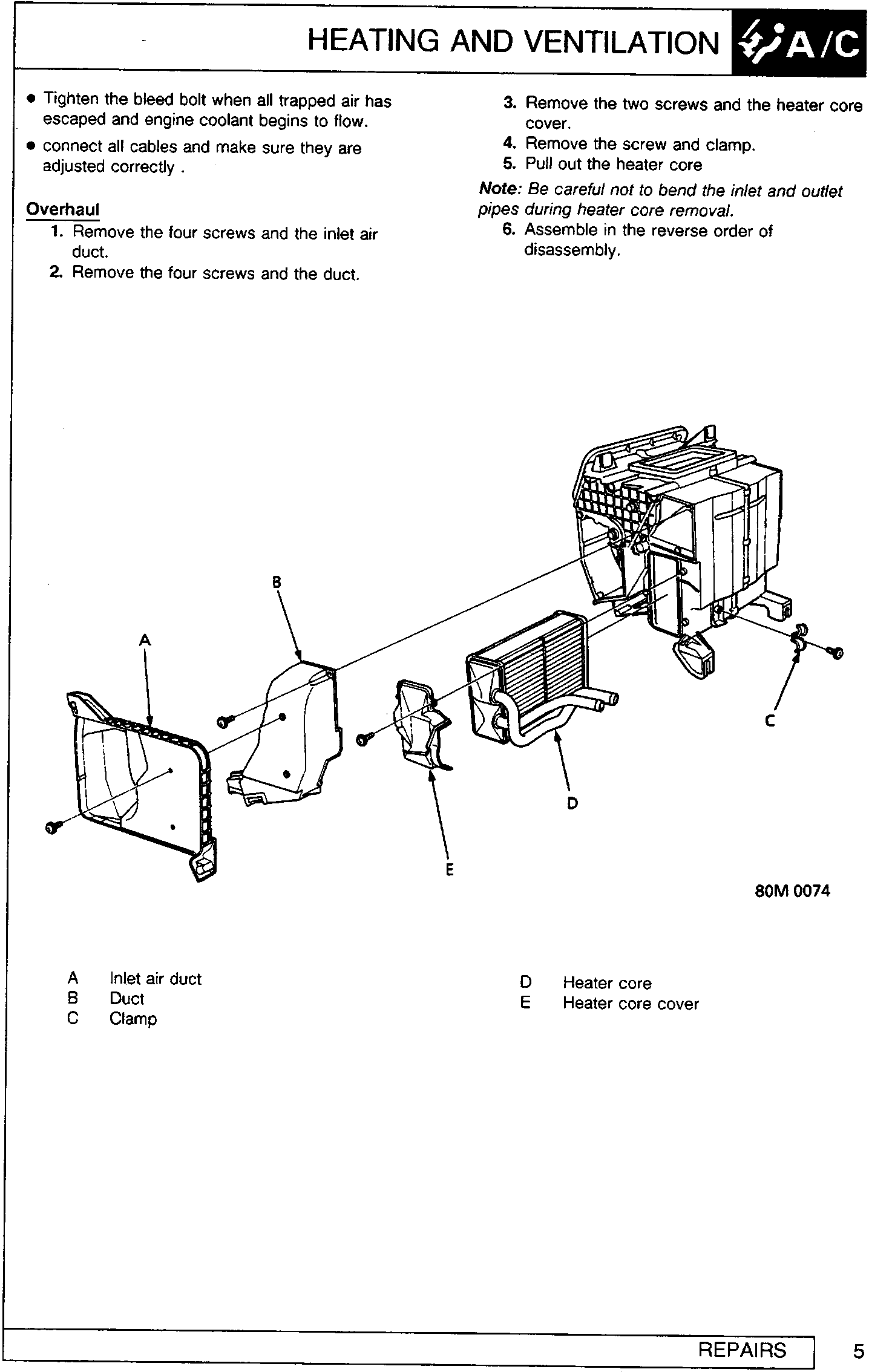
- A Inlet air duct
- B Duct
- C Clamp
- D Heater core
- E Heater core cover
Parts & tools for this job For Rover 600
- TOOLA/C manifold gauge setSearch: AC manifold gauge set
- TOOLUV leak detection kitSearch: AC UV leak detection kit
- PARTCabin filterSearch: Rover 600 cabin filter
Links open Amazon search results in a new tab. As an Amazon Associate I earn from qualifying purchases.