
To adjust the control rod:
- Make
- Rover
- Model
- 600 Rover 600 Repair Manual - Volumes 1 and 2 - 2nd Edition
- Section
- Repairs › To adjust the control rod:
Heating and ventilationTo adjust the control rod:
Note:
- Before assembly, make sure that the recirculation doors and linkage move smoothly without binding.
- When reattaching the recirculation motor, make sure its positioning will not allow the recirculation control doors to be pulled too far. Attach the recirculation control motor and all linkage, then connect power and earth, and watch the movement of the recirculation control doors.
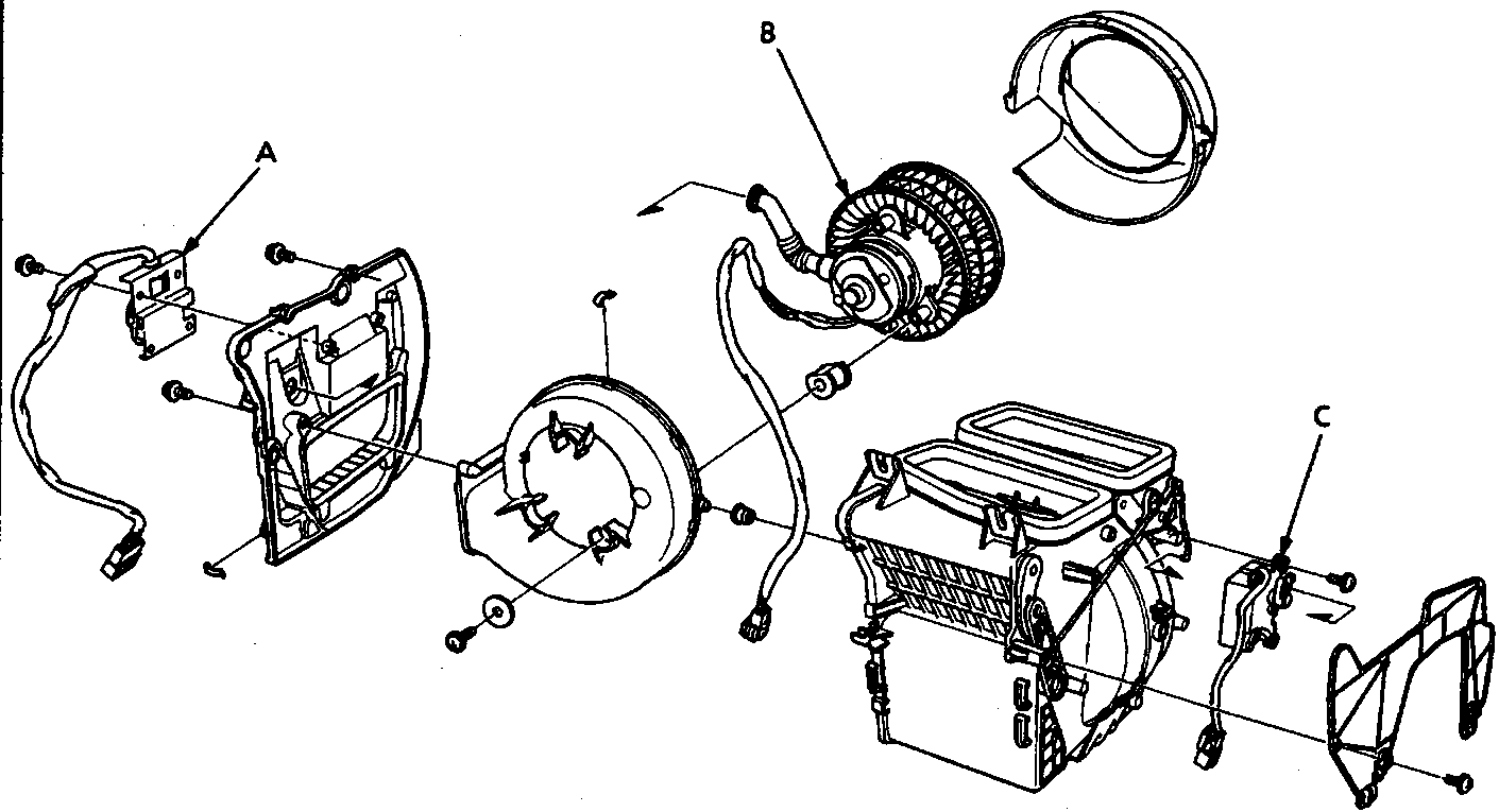
80M 0069
A Blower resistor
B Blower motor
C Recirculation control motor
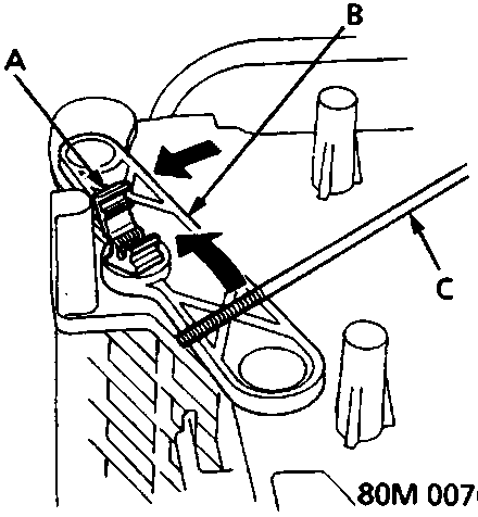
80M 0070
A Clip
B Control arm
C Control rod
To adjust the control rod:
Connect the recirculation control motor connector to the main wire harness and turn the recirculation control switch to FRESH. Close the recirculation control door by turning the control arm as shown and holding it. Then connect the control rod clip.
Parts & tools for this job For Rover 600
- TOOLA/C manifold gauge setSearch: AC manifold gauge set
- TOOLUV leak detection kitSearch: AC UV leak detection kit
- PARTCabin filterSearch: Rover 600 cabin filter
Links open Amazon search results in a new tab. As an Amazon Associate I earn from qualifying purchases.