
Defrost Door Adjustment
- Make
- Rover
- Model
- 600 Rover 600 Repair Manual - Volumes 1 and 2 - 2nd Edition
- Section
- Repairs › Defrost Door Adjustment
Heating and ventilationDefrost Door Adjustment · page 1 of 3
Defrost Door Adjustment
- Set the mode control knob to VENT.
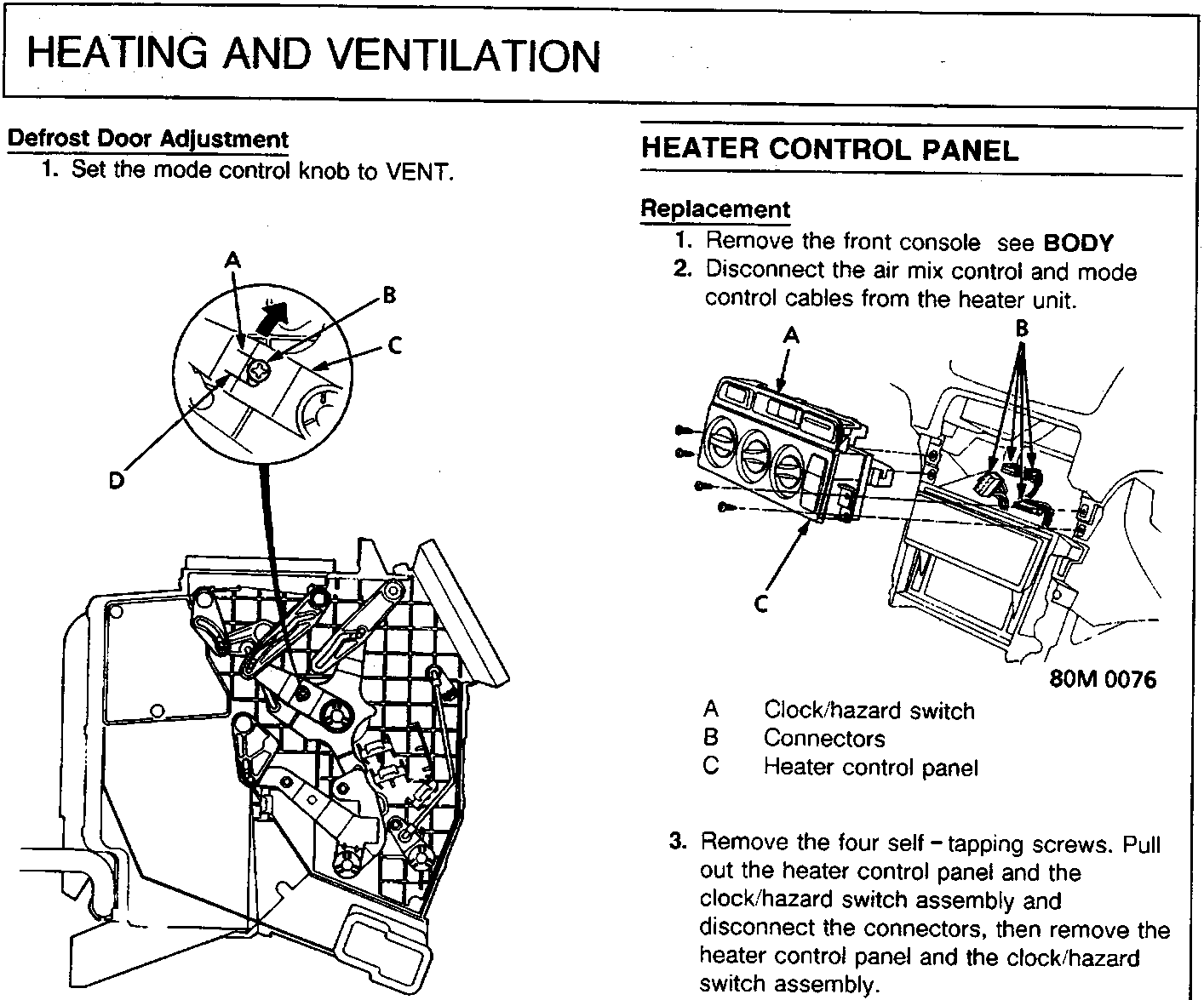
80M 0075
- A Shut position
- B Adjusting screw
- C Control arm
- D 20% position
- Loosen the adjusting screw.
- Turn the control arm to the right as shown, so that there will be a heat leakage of 20% from the defroster door.
- Tighten the adjusting screw.
HEATER CONTROL PANEL
Replacement
- Remove the front console see BODY
- Disconnect the air mix control and mode control cables from the heater unit.
80M 0076
- A Clock/hazard switch
- B Connectors
- C Heater control panel
- Remove the four self – tapping screws. Pull out the heater control panel and the clock/hazard switch assembly and disconnect the connectors, then remove the heater control panel and the clock/hazard switch assembly.
Note: The locking tab of the heater control panel 10P connector is on the bottom.
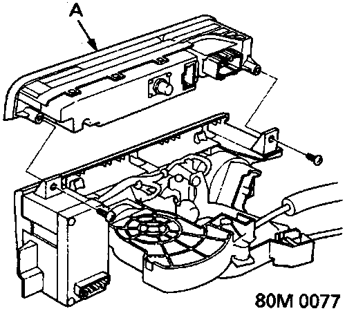
80M 0077
- A Clock/hazard switch
- Remove the two self – tapping screws and clock/hazard switch assembly.
- Install in the reverse order of removal, and adjust the air mix control and mode control cables at the heater unit.
Parts & tools for this job For Rover 600
- TOOLTrim removal tool kitSearch: trim removal tool kit
- PARTTouch-up paintSearch: Rover touch up paint
- PARTPanel clip assortmentSearch: Rover panel clips assortment
Links open Amazon search results in a new tab. As an Amazon Associate I earn from qualifying purchases.