
Heater fan switch
- Make
- Rover
- Model
- 600 Rover 600 Repair Manual - Volumes 1 and 2 - 2nd Edition
- Section
- Repairs › Heater fan switch
Heating and ventilationHeater fan switch · page 1 of 2
HEATER FAN SWITCH
Test
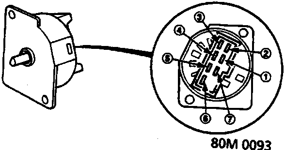
Check for continuity between the terminals according to the table below.
Switch Connection
| Terminal Position | 1 | 2 | 3 | 4 | 5 | 6 | 7 |
|---|---|---|---|---|---|---|---|
| 0 | |||||||
| I | □—□—□ | ||||||
| II | □—□———□ | ||||||
| III | □—□—————————□ | ||||||
| IV | □—□—————————————□ | ||||||
| V | □—□———————————————□ |
RECIRCULATION CONTROL SWITCH
Test
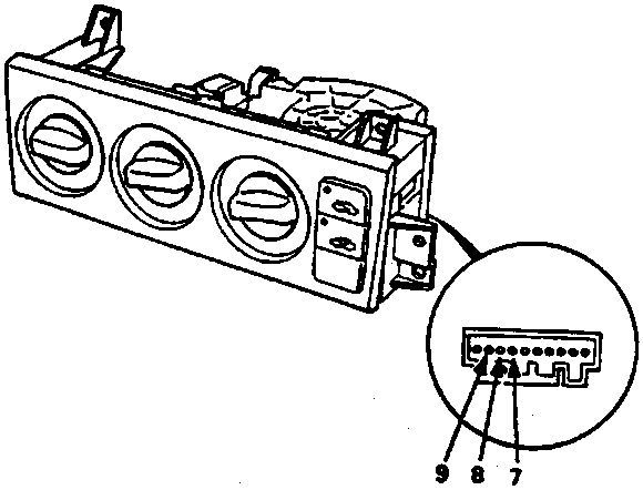
Check for continuity between the terminals according to the table below.
Switch Connection
| Terminal Position | 7 | 8 | 9 |
|---|---|---|---|
| [symbol] | □—————————□ | ||
| [symbol] | □———□ |
Parts & tools for this job For Rover 600
- TOOLOBD2 scannerSearch: OBD2 scanner
- TOOLDigital multimeterSearch: automotive digital multimeter
- TOOLBack-probe test leadsSearch: back probe test leads
Links open Amazon search results in a new tab. As an Amazon Associate I earn from qualifying purchases.