
Replacement
- Make
- Rover
- Model
- 600 Rover 600 Repair Manual - Volumes 1 and 2 - 2nd Edition
- Section
- Repairs › Replacement
Heating and ventilationReplacement
Replacement
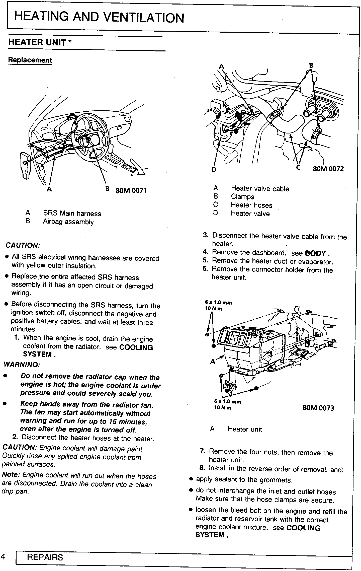
A SRS Main harness
B Airbag assembly
CAUTION:
- All SRS electrical wiring harnesses are covered with yellow outer insulation.
- Replace the entire affected SRS harness assembly if it has an open circuit or damaged wiring.
- Before disconnecting the SRS harness, turn the ignition switch off, disconnect the negative and positive battery cables, and wait at least three minutes.
- When the engine is cool, drain the engine coolant from the radiator, see COOLING SYSTEM.
WARNING:
- Do not remove the radiator cap when the engine is hot; the engine coolant is under pressure and could severely scald you.
- Keep hands away from the radiator fan. The fan may start automatically without warning and run for up to 15 minutes, even after the engine is turned off.
- Disconnect the heater hoses at the heater.
CAUTION: Engine coolant will damage paint. Quickly rinse any spilled engine coolant from painted surfaces.
Note: Engine coolant will run out when the hoses are disconnected. Drain the coolant into a clean drip pan.
A Heater valve cable
B Clamps
C Heater hoses
D Heater valve
- Disconnect the heater valve cable from the heater.
- Remove the dashboard, see BODY.
- Remove the heater duct or evaporator.
- Remove the connector holder from the heater unit.
A Heater unit
- Remove the four nuts, then remove the heater unit.
- Install in the reverse order of removal, and:
- apply sealant to the grommets.
- do not interchange the inlet and outlet hoses. Make sure that the hose clamps are secure.
- loosen the bleed bolt on the engine and refill the radiator and reservoir tank with the correct engine coolant mixture, see COOLING SYSTEM.
Parts & tools for this job For Rover 600
- TOOLA/C manifold gauge setSearch: AC manifold gauge set
- TOOLUV leak detection kitSearch: AC UV leak detection kit
- PARTCabin filterSearch: Rover 600 cabin filter
Links open Amazon search results in a new tab. As an Amazon Associate I earn from qualifying purchases.