
Reverse shift fork
- Make
- Rover
- Model
- 600 Rover 600 Repair Manual - Volumes 1 and 2 - 2nd Edition
- Section
- Repairs › Reverse shift fork
Manual gearboxReverse shift fork
- Separate the gearbox housing from the clutch housing and wipe it clean of the sealant.
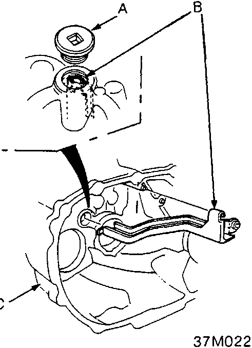
- A Sealing bolt
- B Oil gutter plate
- C Gearbox housing
- Remove the 28 mm sealing bolt, then remove the oil gutter plate.
Note: The gearbox housing can be removed with the oil gutter plate in the gearbox housing.
REVERSE SHIFT FORK
Clearance Inspection
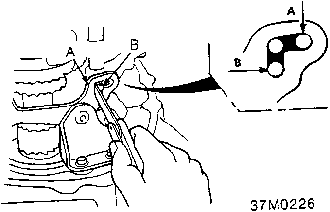
- A Reverse shift fork
- B 5th/reverse shift piece pin
- Measure the clearance between the reverse shift fork and 5th/reverse shift piece pin.
Standard:
A:0.05 – 0.35 mm
B: 0.4 – 0.8 mm
Service Limit:
A: 0.5 mm
B:1.0 mm
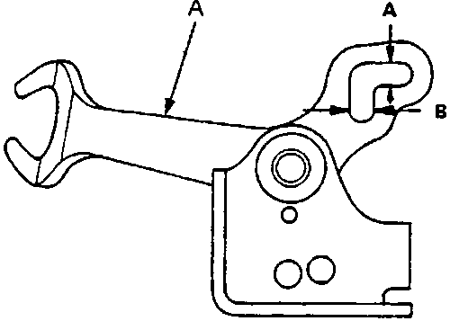
- A Reverse shift fork
- If the clearance exceeds the service limit, measure the width of the groove in the reverse shift fork.
Standard:
A: 7.05 – 7.25 mm
B: 7.4 – 7.7 mm
Parts & tools for this job For Rover 600
- PARTClutch kitSearch: Rover 600 clutch kit
- TOOLClutch alignment toolSearch: clutch alignment tool
- FLUIDGear oilSearch: Rover 600 manual gearbox oil
Links open Amazon search results in a new tab. As an Amazon Associate I earn from qualifying purchases.