
Reverse light switch
- Make
- Rover
- Model
- 600 Rover 600 Repair Manual - Volumes 1 and 2 - 2nd Edition
- Section
- Repairs › Reverse light switch
Manual gearboxReverse light switch · page 1 of 10
REVERSE LIGHT SWITCH
Renew
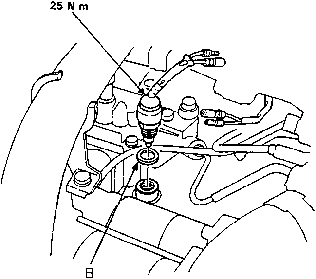
- A Reverse Light Switch
- B Washer
To test the reverse light switch, see ELECTRICAL.
- Disconnect the reverse light switch.
- Remove the reverse light switch.
- Install the new washer and reverse light switch.
- Connect the reverse light switch connectors.
GEARBOX
Remove
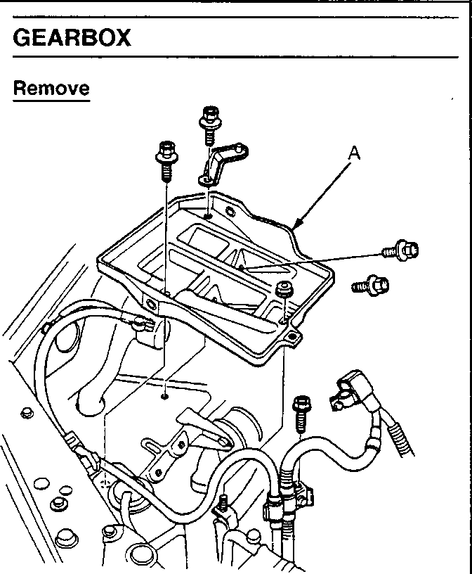
- A Battery Base
- Raise front of vehicle.
- WARNING: Support on safety stands. Disconnect the negative (−) and positive (+) cables from the battery, then remove the battery.
- Drain the gearbox oil.
- Remove the battery base.
Parts & tools for this job For Rover 600
- TOOLOBD2 scannerSearch: OBD2 scanner
- TOOLDigital multimeterSearch: automotive digital multimeter
- TOOLBack-probe test leadsSearch: back probe test leads
Links open Amazon search results in a new tab. As an Amazon Associate I earn from qualifying purchases.