
Reverse light switch (page 3 of 10)
- Make
- Rover
- Model
- 600 Rover 600 Repair Manual - Volumes 1 and 2 - 2nd Edition
- Section
- Repairs
Manual gearboxReverse light switch · page 3 of 10
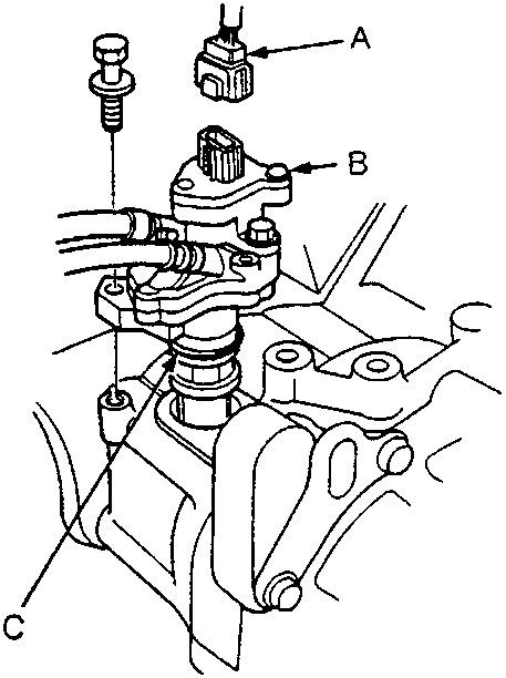
A Vehicle speed sensor connector
B Vehicle steering speed sensor
C O-ring – Replace
- Disconnect the vehicle speed sensor connector and remove the vehicle steering speed sensor, but leave its hoses connected.
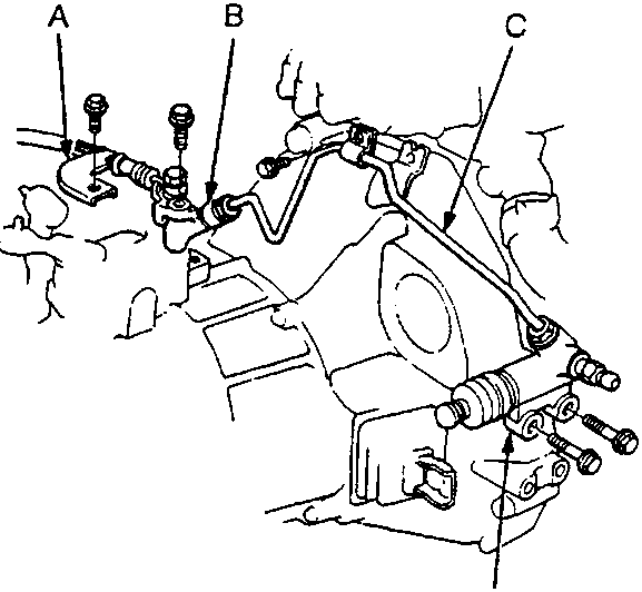
A Stay
B Clutch Hose Joint
C Clutch Pipe
D Slave Cylinder
- Remove the slave cylinder, clutch pipe, clutch hose joint and stay from the gearbox, see CLUTCH.
Note:
- Do not operate the clutch pedal once the slave cylinder has been removed.
- Take care not to bend the clutch pipe.
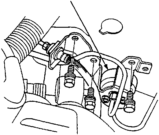
A Clutch Damper
- Remove the clutch damper mounting bolts, and raise the clutch damper.
Note: Do not disconnect the clutch pipe.
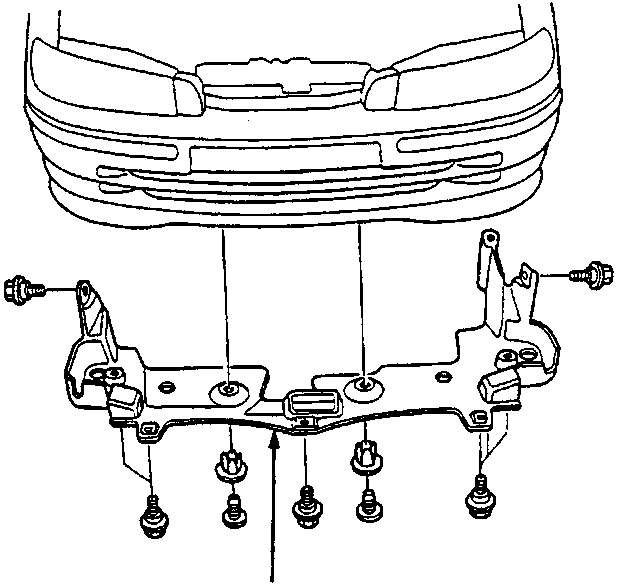
A Engine Splash Shield
- Remove the engine splash shield.
Parts & tools for this job For Rover 600
- TOOLOBD2 scannerSearch: OBD2 scanner
- TOOLDigital multimeterSearch: automotive digital multimeter
- TOOLBack-probe test leadsSearch: back probe test leads
Links open Amazon search results in a new tab. As an Amazon Associate I earn from qualifying purchases.