
Inspection
- Make
- Rover
- Model
- 600 Rover 600 Repair Manual - Volumes 1 and 2 - 2nd Edition
- Section
- Repairs › Inspection
Manual gearboxInspection
Inspection
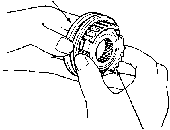
37M0269
| A | Synchro sleeve |
| B | Synchro hub |
- Inspect gear teeth on all synchro hubs and synchro sleeves for rounded off corners, which indicates wear.
- Install each synchro hub in its mating synchro sleeve and check for freedom of movement.
Note: If replacement is required, always replace the synchro sleeve and synchro hub as a set.
Installation
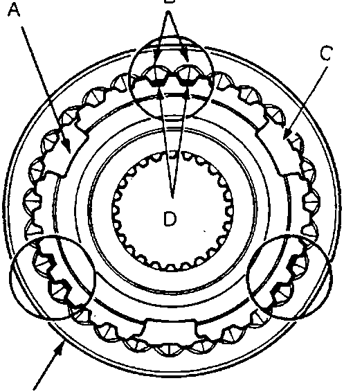
37M0270
| A | Synchro hub |
| B | Longer teeth |
| C | Synchro hub slot |
| D | Deeper grooves |
| E | Synchro sleeve |
When assembling the synchro sleeve and synchro hub, be sure to match the three sets of longer teeth (120 degrees apart) on the synchro sleeve with the three sets of deeper grooves in the synchro hub.
CAUTION: Do not install the synchro sleeve with its longer teeth in the 1st/2nd synchro hub slots, because it will damage the spring ring.
Parts & tools for this job For Rover 600
- PARTClutch kitSearch: Rover 600 clutch kit
- TOOLClutch alignment toolSearch: clutch alignment tool
- FLUIDGear oilSearch: Rover 600 manual gearbox oil
Links open Amazon search results in a new tab. As an Amazon Associate I earn from qualifying purchases.