
Disassembly/Reassembly
- Make
- Rover
- Model
- 600 Rover 600 Repair Manual - Volumes 1 and 2 - 2nd Edition
- Section
- Repairs › Disassembly/Reassembly
Manual gearboxDisassembly/Reassembly · page 1 of 3
Disassembly/Reassembly
6 x 1.0 mm
12 N m
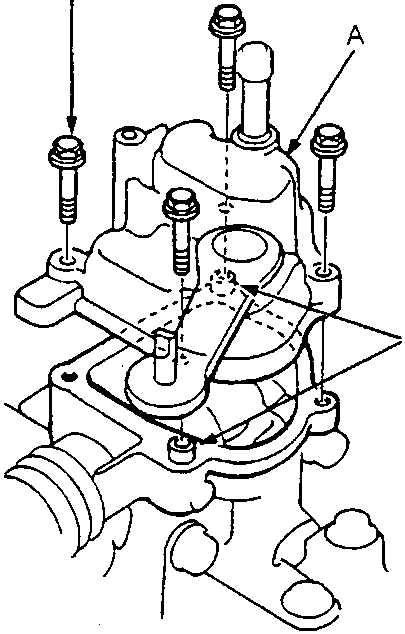
- A Shift arm cover assembly
- B Dowel pins
Note: During reassembly, grease all sliding parts.
- Remove the shift arm cover assembly
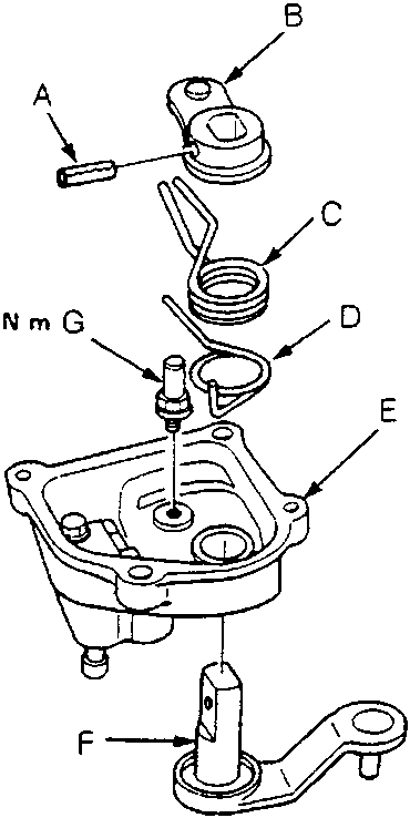
- A Spring pin
- B Select arm
- C Select return spring
- D 5th/reverse select spring
- E Shift arm cover
- F Select lever
- G Select return pin
- Remove the spring pin – replace, then remove the select lever, select arm, and springs.
- Remove the select return pin.
Parts & tools for this job For Rover 600
- PARTClutch kitSearch: Rover 600 clutch kit
- TOOLClutch alignment toolSearch: clutch alignment tool
- FLUIDGear oilSearch: Rover 600 manual gearbox oil
Links open Amazon search results in a new tab. As an Amazon Associate I earn from qualifying purchases.