
Reverse light switch (page 7 of 10)
- Make
- Rover
- Model
- 600 Rover 600 Repair Manual - Volumes 1 and 2 - 2nd Edition
- Section
- Repairs
Manual gearboxReverse light switch · page 7 of 10
- Inspect rubber parts for wear and damage when disassembling.
- Replace all cotter pins, self locking nuts and O – rings. Check that the new cotter pin is seated firmly.
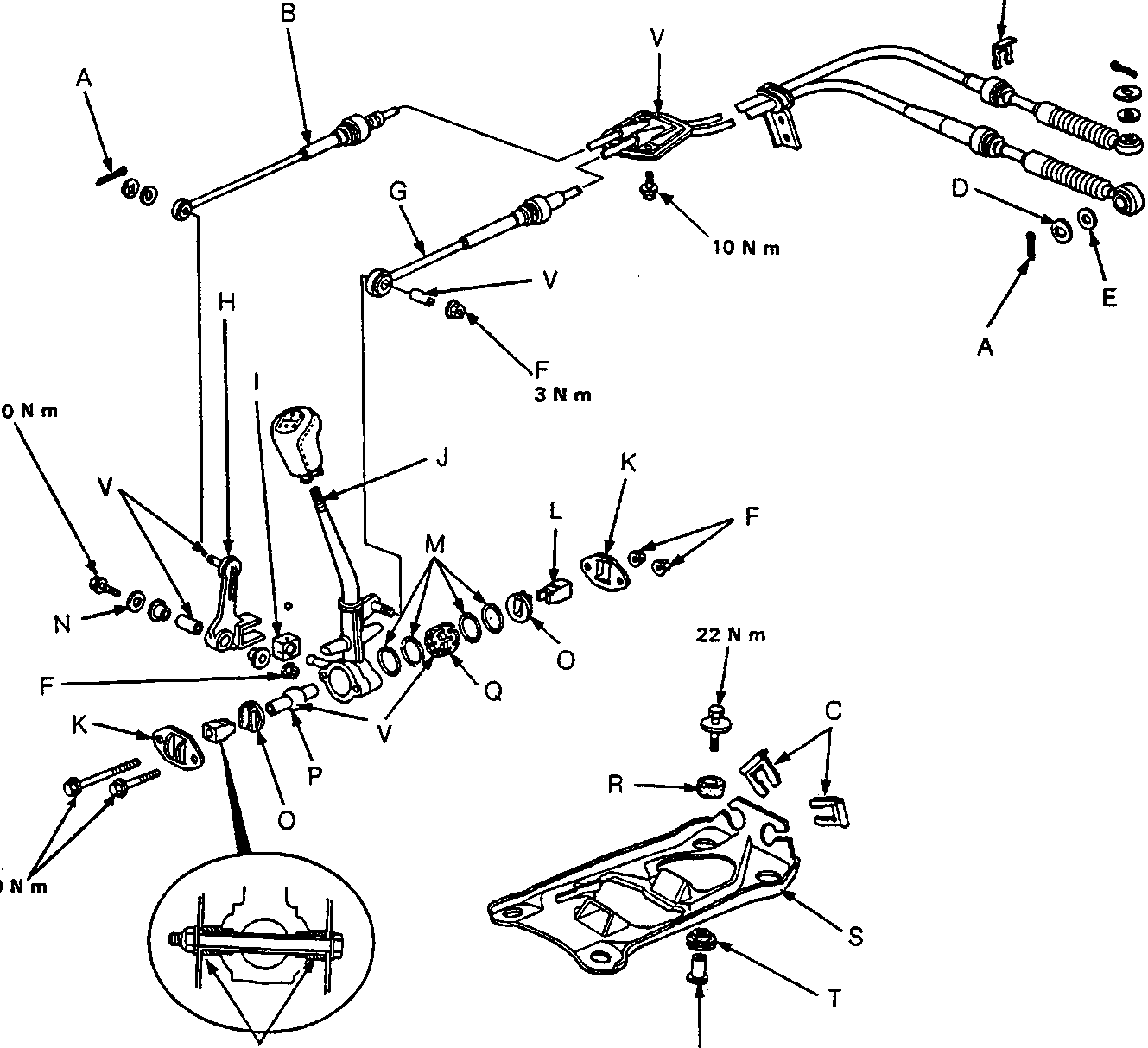
37M0211
| A | Cotter pin | I | Change lever bush C | Q | Change lever ball seat |
| B | Select cable | J | Change lever | R | Floating rubber A |
| C | Change wire plate | K | Change ball holder | S | Change lever bracket |
| D | Steel washer | L | Pivot bushing | T | Floating rubber B |
| E | Plastic washer | M | O – rings | U | Floating collar |
| F | Self – locking nut | N | Wave washer | V | Grease |
| G | Shift cable | O | Change pivot guide | W | Pivot bushing |
| H | Change lever linkage | P | Change lever pivot |
Parts & tools for this job For Rover 600
- TOOLOBD2 scannerSearch: OBD2 scanner
- TOOLDigital multimeterSearch: automotive digital multimeter
- TOOLBack-probe test leadsSearch: back probe test leads
Links open Amazon search results in a new tab. As an Amazon Associate I earn from qualifying purchases.