
Reverse light switch (page 5 of 10)
- Make
- Rover
- Model
- 600 Rover 600 Repair Manual - Volumes 1 and 2 - 2nd Edition
- Section
- Repairs
Manual gearboxReverse light switch · page 5 of 10
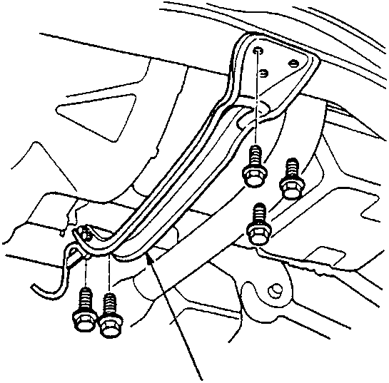
A Centre beam
- Remove the centre beam.
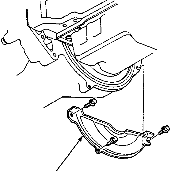
A Clutch case cover
- Remove the clutch case cover.
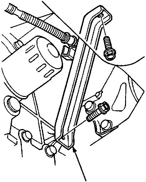
A Intake manifold stay.
- Remove the intake manifold stay.
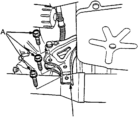
A Mounting bolts
B Rear engine mount bracket.
- Remove the three rear engine mount bracket bolts – replace.
- Place a jack under the gearbox and raise the gearbox just enough to take weight off the mounts.
Parts & tools for this job For Rover 600
- TOOLOBD2 scannerSearch: OBD2 scanner
- TOOLDigital multimeterSearch: automotive digital multimeter
- TOOLBack-probe test leadsSearch: back probe test leads
Links open Amazon search results in a new tab. As an Amazon Associate I earn from qualifying purchases.