
Components (page 2 of 5)
- Make
- Rover
- Model
- 600 Rover 600 Repair Manual - Volumes 1 and 2 - 2nd Edition
- Section
- Repairs
SuspensionComponents · page 2 of 5
- Remove the caliper bracket mounting bolts and suspend the caliper to one side.
CAUTION: To prevent accidental damage to the caliper or brake hose, use a short piece of wire to suspend the caliper.
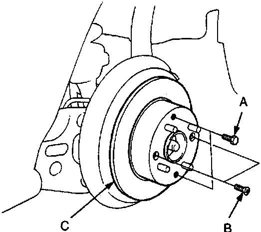
60M 0106
- A Bolts
- B 6 mm brake disc retaining screws
- C Brake disc
- Remove the 6mm brake disc retaining screws.
- Screw two 8 x 1.25mm bolts into the disc to push it away from the hub.
Note: Turn each bolt in increments (two turns each) to ensure that the disc does not lock up on the hub.
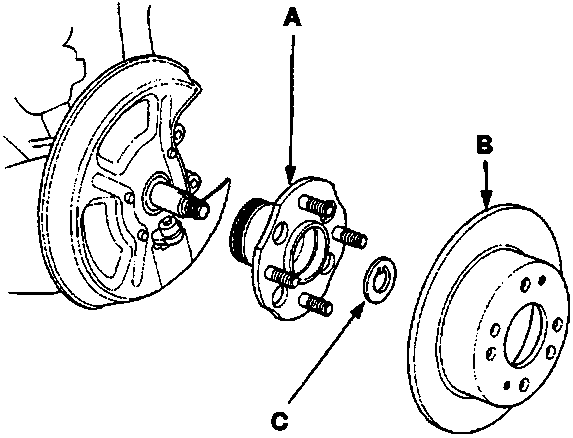
60M 0107
- A Hub unit
- B Brake disc
- C Spindle washer
- Remove the brake disc.
- Remove the hub unit from the knuckle.
- Check the hub unit for cracks or damage.
- Check the brake disc for wear or rust, see BRAKES
Parts & tools for this job For Rover 600
- TOOLCoil spring compressorSearch: coil spring compressor
- TOOLBall joint separatorSearch: ball joint separator
- PARTShock absorbersSearch: Rover 600 shock absorbers
Links open Amazon search results in a new tab. As an Amazon Associate I earn from qualifying purchases.