
Components (page 4 of 5)
- Make
- Rover
- Model
- 600 Rover 600 Repair Manual - Volumes 1 and 2 - 2nd Edition
- Section
- Repairs
SuspensionComponents · page 4 of 5
185 Nm
110 Nm
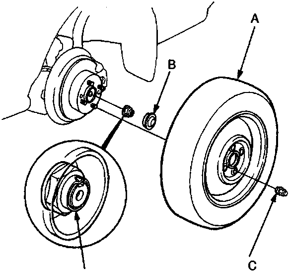
- Rear wheel
- Hub cap
- Wheel nut
- Spindle nut
- Tighten the new spindle nut. After tightening, stake the spindle nut shoulder against the spindle.
- Install the new hub cap.
Note: Before installing the wheel, clean the mating surfaces of the brake disc and inside of the wheel.
- Install the rear wheel with the wheel nuts.
Parts & tools for this job For Rover 600
- TOOLCoil spring compressorSearch: coil spring compressor
- TOOLBall joint separatorSearch: ball joint separator
- PARTShock absorbersSearch: Rover 600 shock absorbers
Links open Amazon search results in a new tab. As an Amazon Associate I earn from qualifying purchases.