
Refit
- Make
- Rover
- Model
- Coupé, Cabriolet & Tourer 200/400 Coupé, Cabriolet & Tourer Workshop Manual
- Section
- Repairs › Refit
Engine management system - PGM-FiRefit
- Remove resonator.
Do not carry out further dismantling if component is removed for access only
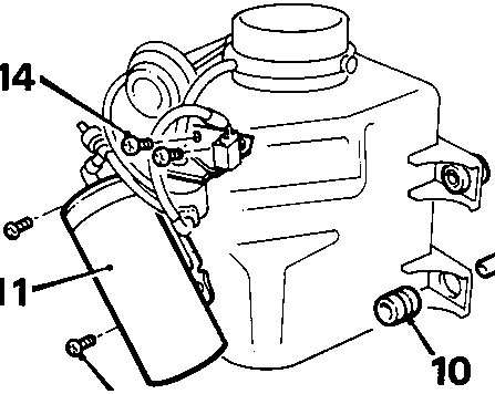
- Remove 3 spacers.
- Remove 3 rubber mountings.
- Release vacuum tank from bracket.
- Remove 2 screws securing tank bracket.
- Remove bracket.
- Remove 2 screws securing solenoid bracket.
- Remove bracket.
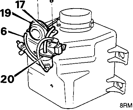
- Disconnect vacuum hose from diaphragm assembly.
- Release vacuum hose from sensor pipe.
- Remove 2 screws securing diaphragm assembly.
- Remove diaphragm.
- Remove joint assembly from resonator.
Refit
- Fit joint assembly to resonator.
- Position diaphragm assembly, fit and tighten 2 screws.
- Position solenoid bracket, fit and tighten 2 screws.
- Connect 2 vacuum hoses.
- Position vacuum tank bracket, fit and tighten 2 screws.
- Clip vacuum tank into bracket.
- Fit 3 rubber mountings and 3 spacers.
- Align resonator with intake pipe and valance, fit and tighten 3 bolts.
- Connect multiplug and vacuum hose.
- Refit front bumper, see BODY – Repairs.
- Remove stands and lower vehicle.
- Connect battery earth lead.
DASHPOT DIAPHRAGM
Service Repair No. 19.22.58
Remove
- Disconnect battery earth lead.
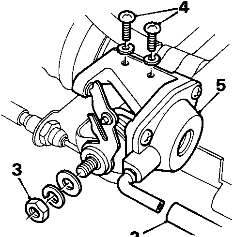
- Disconnect vacuum hose from dashpot diaphragm.
- Remove throttle lever nut and washers.
- Remove 2 screws and washers securing dashpot diaphragm to throttle body.
- Remove dashpot diaphragm and lever assembly.
Parts & tools for this job For Rover Coupé, Cabriolet & Tourer
- PARTEngine gasket setSearch: Rover Coupé, Cabriolet & Tourer engine gasket set
- TOOLTorque wrenchSearch: 3/8 inch torque wrench
- TOOLFeeler gauge setSearch: feeler gauge set
Links open Amazon search results in a new tab. As an Amazon Associate I earn from qualifying purchases.