
Refit
- Make
- Rover
- Model
- Coupé, Cabriolet & Tourer 200/400 Coupé, Cabriolet & Tourer Workshop Manual
- Section
- Repairs › Refit
Engine management system - PGM-FiRefit · page 1 of 2
Refit
- Clean housing and manifold mating faces and fit new gasket.
- Position housing in vehicle, connect 3 coolant hoses and secure with clips.
- Position housing onto studs, fit and tighten 3 nuts and 1 bolt to 22 Nm.
- Automatic gearbox only: Connect throttle control cable trunnion to cam.
- Automatic gearbox only: Connect throttle control cable to abutment bracket and adjust cable, see AUTOMATIC GEARBOX 1.6 – Adjustments.
- Connect throttle cable trunnion.
- Connect multiplug to throttle potentiometer.
- Reconnect intake hose to throttle housing and tighten securing clip.
- Top – up cooling system, see MAINTENANCE.
- Connect battery earth lead.
- Adjust throttle cable, see Adjustments.
- Check ignition timing, see MAINTENANCE.
- Set idle speed and mixture, see MAINTENANCE.
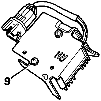
8RM 1278
INJECTORS RESISTOR PACK
Service Repair No. 80.30.04
Remove
- Disconnect battery earth lead.
- Remove washer reservoir from bulkhead, see WIPERS AND WASHERS – Repairs.
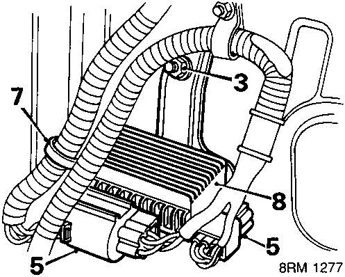
8RM 1277
- Remove nut and washer securing resistor to bulkhead.
- Release resistor from bulkhead.
- Disconnect 2 multiplugs.
- Release 2 multiplugs from clips on bracket.
- Release harness from clip on bracket.
- Remove resistor and bracket assembly.
- Remove 2 screws and washers securing resistor to bracket.
- Remove resistor from bracket.
Refit
- Fit resistor to bracket, fit washers and 2 screws and tighten screws.
- Secure multiplugs to brackets.
- Clip harness to bracket.
- Connect 2 multiplugs.
- Position resistor to bulkhead, fit washer and nut to stud and tighten nut.
- Fit washer reservoir to bulkhead, see WIPERS AND WASHERS – Repairs.
- Connect battery earth lead.
INJECTOR
Service Repair No. 19.60.10
Remove
- Disconnect battery earth lead.
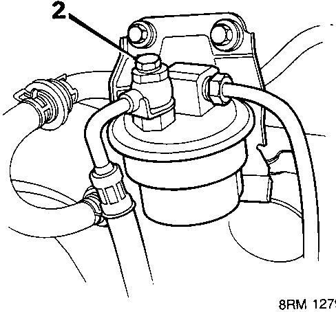
8RM 1279
- Position absorbent cloth around sealing bolt. Slacken bolt to relieve fuel pressure. Retighten bolt to 12 Nm.
Parts & tools for this job For Rover Coupé, Cabriolet & Tourer
- PARTEngine gasket setSearch: Rover Coupé, Cabriolet & Tourer engine gasket set
- TOOLTorque wrenchSearch: 3/8 inch torque wrench
- TOOLFeeler gauge setSearch: feeler gauge set
Links open Amazon search results in a new tab. As an Amazon Associate I earn from qualifying purchases.