
Pedal assembly - r.r
- Make
- Fiat
- Model
- 500 Factory Service Manual
- Year
- 2007–2024
- Section
- Hydraulic braking system › Pedal assembly - r.r
PEDAL ASSEMBLY - R.R
Removing
Before working on the air bag system, it is essential to perform the following preliminary operations.
(1) turn the ignition key to the OFF position and extract it;
(2) disconnect the battery terminals and insulate them;
(3) wait for at least 10 minutes before continuing.
FOLLOW ALL THE RECOMMENDED SAFETY INSTRUCTIONS
Op. 7040A26 STEERING COLUMN TRIM - R+R
- If the vehicle is equipped with knee bags
Op. 5580C23 DRIVER'S KNEE BAG - R.R.
Op. 7040A30
Op. 5580C18 AIR BAG MODULE - R+R
Op. 4110A10 STEERING WHEEL - R+R FOR REPLACEMENT OR CHECKS
Op. 5550A10 STALK UNIT ASSEMBLY - R+R
Op. 4110D20 STEERING ELECTRICAL CONTROL DEVICE - R R
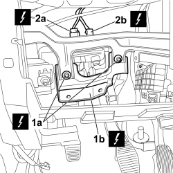
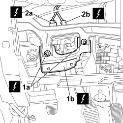
1. Undo the fixing bolts (1a) and remove the reinforcement bracket (1b).
2. Disconnect the electrical connections for the switch on the clutch pedal (2a) and on the brake pedal (2b).
| Description | Connector | |
|---|---|---|
| 2a | BRAKE PEDAL SWITCH | See I030 BRAKE PEDAL SWITCH |
| Description | Connector | |
|---|---|---|
| 2b | CLUTCH PEDAL SWITCH | See I031 CLUTCH PEDAL SWITCH |
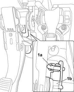
1. Disconnect the end of the release control cable (1a) from the clutch pedal (1b).
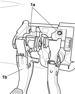
1. Undo the nuts (1a) securing the pedal assembly (1b) to the body.
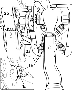
1. Release the retaining tabs (1a) and release the brake servo control push rod (1b) from the brake pedal.
2. Undo the nuts (2a) securing the brake servo to the pedal assembly and remove the pedal assembly (2b).
Refitting
- Fit the pedal assembly in place and tighten the fixing nuts to the bodyshell.
1. Tighten the nuts fixing the brake servo to the pedal assembly to the recommended torque.
| Component | Fastening | dia | Value (daNm) | Validity |
|---|---|---|---|---|
| Brake servo pedal unit | Nut | M8 | 2.2 | T.i.T |
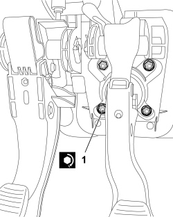
- Connect the brake servo control push rod to the brake pedal and attach the retaining device tabs.
- Connect the end of the release control cable to the clutch pedal.
1. Connect the electrical connections for the switch to the clutch pedal (1a) and to the brake pedal (1b).
| Description | Connector | |
|---|---|---|
| 1a | BRAKE PEDAL SWITCH | See I030 BRAKE PEDAL SWITCH |
| Description | Connector | |
|---|---|---|
| 1b | CLUTCH PEDAL SWITCH | See I031 CLUTCH PEDAL SWITCH |
2. Fit the mounting bracket (2a) and tighten the fixing bolt (2b).
Op. 4110D20 STEERING ELECTRICAL CONTROL DEVICE - R R
Op. 5550A10 STALK UNIT ASSEMBLY - R+R
Op. 4110A10 STEERING WHEEL - R+R FOR REPLACEMENT OR CHECKS
Op. 5580C18 AIR BAG MODULE - R+R
Op. 7040A30
- If the vehicle is equipped with knee bags
Op. 5580C23 DRIVER'S KNEE BAG - R.R.
Op. 7040A26 STEERING COLUMN TRIM - R+R
- Connect the battery terminals.
| Description | Connector | |
|---|---|---|
| BATTERY | See A001 BATTERY |
Parts & tools for this job For 2007 Fiat 500
- PARTBrake padsSearch: Fiat 500 2007 brake pads
- TOOLBrake bleeder kitSearch: one man brake bleeder kit
- FLUIDBrake fluidSearch: brake fluid
Links open Amazon search results in a new tab. As an Amazon Associate I earn from qualifying purchases.