
Inertial safety switch
- Make
- Fiat
- Model
- Bravo /Brava (182) Factory Service Manual
- Year
- 1995–2001
- Section
- Fuel system (98 range, 1581 16v) › Inertial safety switch
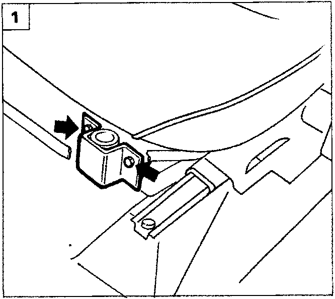
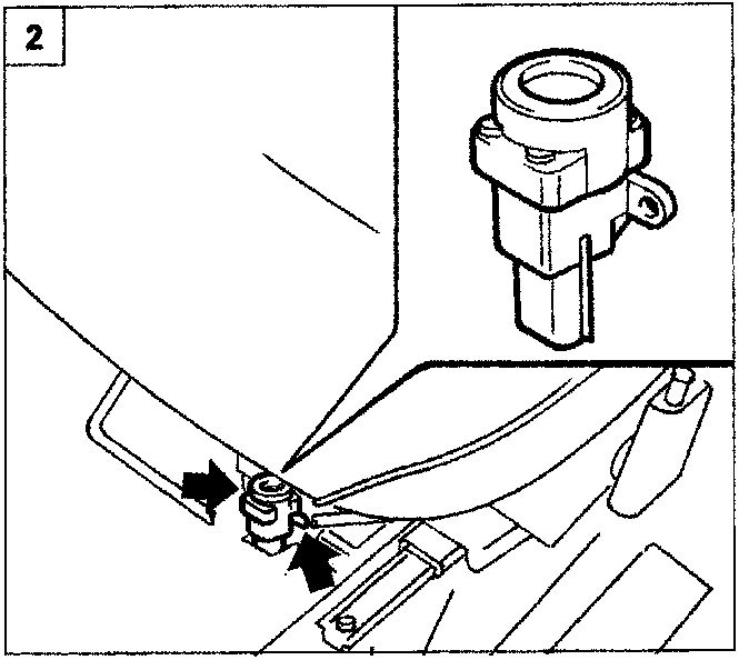
INERTIAL SAFETY SWITCH
In order to increase the safety for the vehicle’s occupants in a crash, the car has an inertial switch located in the interior compartment under the driver’s seat.
This sensor reduces the possibility of fire (caused by fuel leaking from the fuel injection system) by disabling the fuel pump which feeds the injection circuit.
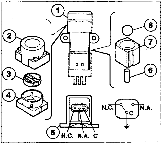
The switch consists of a steel ball mounted in a housing (conical seating) and held in position by the force of attaction of a permanent magnet.
In the event of a violent crash of the vehicle, the ball is released from the magnetic stop and it opens the normally closed (N.C.) electrical circuit, interrupting the earth connection of the fuel pump and consequently the feed to the fuel injection system.
To restore the fuel pump’s earth connection, push back the seat and press on the switch until you hear it engage.
Removing-refitting
- Push the driver’s seat back fully, undo the bolts indicated and remove the plastic cover.
- Undo the bolts indicated, disconnect the wiring connection and remove the switch.
After a crash, even if apparently minor, if the smell of fuel is perceived or there are leaks from the fuel system, do not reset the switch until you have found and eliminated the fault, in order to avoid the risk of fire.
Components constituting the inertial switch
- Complete inertial switch
- Sheath
- Button
- Top
- Engagement side.
- Permanent magnet
- Permanent magnet seating
- Steel ball
C= Shared terminal
N.C. Normally closed
N.A. Normally open

Parts & tools for this job For 1995 Fiat Bravo
- TOOLOBD2 scannerSearch: OBD2 scanner
- TOOLDigital multimeterSearch: automotive digital multimeter
- TOOLBack-probe test leadsSearch: back probe test leads
Links open Amazon search results in a new tab. As an Amazon Associate I earn from qualifying purchases.