
Motor strategy
- Make
- Fiat
- Model
- Bravo /Brava (182) Factory Service Manual
- Year
- 1995–2001
- Section
- Fuel system (98 range, 1581 16v) › Motor strategy
‹ Prev ENGINE IDLE SPEED ACTUATOR (step motor)Next › Intake air pressure and temperature sensor (T-PRT 03)
10 EngineMotor strategy
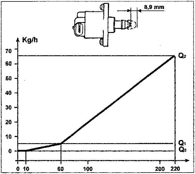
Motor strategy
The number of working steps depends on engine condition: - Ignition stage When the ignition key is inserted, the control unit makes the step motor take up a position dependent upon coolant temperature and battery voltage. - Warm-up stage RPM is adjusted according to coolant temperature - With engine warm: Idle management depends on a signal from the engine rpm sensor. The control unit manages sustained idle mode when external loads are activated. - During deceleration The electronic control unit identifies deceleration stage from throttle potentiometer position. It controls step motor position via the idle flow law (dashpot law), i.e. it slows the return of plunger (3) to its seat so that a quantity of air bypassed from hole (2) reaches the motor and reduces levels of pollutants in exhaust gases.Recovery
Actuator operation disabled, fuel vapour recirculation self-adaptation inhibited and speed limited to 1200 rpm.Removing-refitting engine idle speed actuator (step motor)
Procedure for premodification cars - disconnect the battery negative terminal. - unscrew both retaining bolts and withdraw the actuator; - check the condition of the o-ring and remove any impurities from the seat in the case; - refit the actuator and check that the plunger fits properly into its seat without forrcing.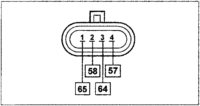
Connector wiring
The numbers in squares indicate the control unit pins.‹ Prev ENGINE IDLE SPEED ACTUATOR (step motor)Next › Intake air pressure and temperature sensor (T-PRT 03)
Parts & tools for this job For 1995 Fiat Bravo
- PARTFuel filterSearch: Fiat Bravo 1995 fuel filter
- TOOLFuel pressure test kitSearch: fuel pressure test kit
- TOOLFuel line disconnect toolSearch: fuel line disconnect tool
Links open Amazon search results in a new tab. As an Amazon Associate I earn from qualifying purchases.