
Removing-refitting
- Make
- Fiat
- Model
- Bravo /Brava (182) Factory Service Manual
- Year
- 1995–2001
- Section
- Fuel system (98 range, 1581 16v) › Removing-refitting
The sensor is connected to the control unit by means of twisted cables covered by a shielded anti-interference sheath.
Pin 1 - Signal
Pin 2 - Earth
Pin 3 - Shielding
NOTE The numbers in boxes indicate the corresponding control unit pins.
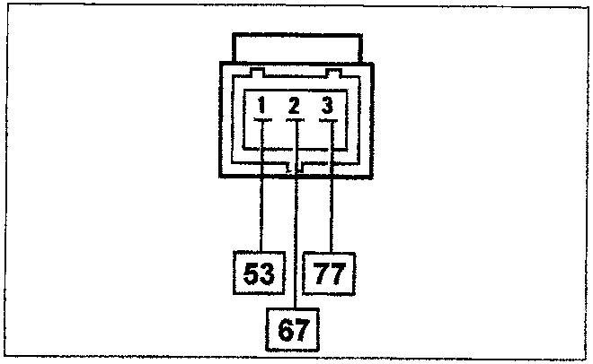
Removing-refitting
Disconnect the wiring connector.
Undo the screw indicated and remove the sensor.
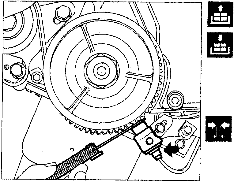
Checking the gap
Check the distance between the sensor and phonic wheel teeth (gap).
Gap: 0.5 - 1.5 mm
NOTE If work has to be done on the rpm and TDC sensor mounting (e.g. gap outside tolerance limits, sensor misaligned, etc.), the procedure must be carried out for correct positioning of the sensor and its mounting, and setting its timing, as described in the engine overhaul manual (publication no. 504.589/20).
Checking resistance
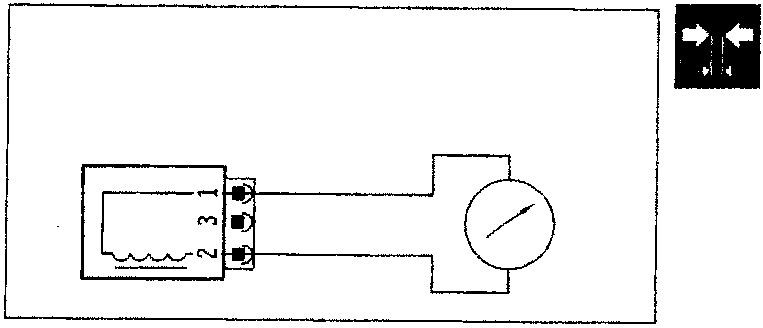
The sensor's resistance can be measured by disconnecting the connector and connecting an ohmmeter to the ends of the sensor.
Resistance 1134 - 1386 ohm at 20 °C
Parts & tools for this job For 1995 Fiat Bravo
- PARTFuel filterSearch: Fiat Bravo 1995 fuel filter
- TOOLFuel pressure test kitSearch: fuel pressure test kit
- TOOLFuel line disconnect toolSearch: fuel line disconnect tool
Links open Amazon search results in a new tab. As an Amazon Associate I earn from qualifying purchases.