
Management of ignition
- Make
- Fiat
- Model
- Bravo /Brava (182) Factory Service Manual
- Year
- 1995–2001
- Section
- Fuel system (98 range, 1581 16v) › Management of ignition
MANAGEMENT OF IGNITION
The ignition circuit is of the static type with inductive discharge, i.e. without high tension distributor with power modules located inside the fuel injection-ignition electronic control unit.
The system has two double-output high tension coils combined in a single container and connected directly to the spark plugs.
The primary winding of each coil is connected to the power relay (so is supplied by the battery voltage) and to the pins of the electronic control unit for the earth connection.
After the engine has started, the electronic control unit manages the basic advance obtained from special mapping in accordance with the following input parameters:
- engine speed (rpm);
- absolute pressure value (mmHg) measured in the inlet manifold.
This advance is corrected in accordance with the temperature of the coolant and intake air.
The value of the advance angle is also corrected under the following conditions:
- during starting;
- in transient acceleration and deceleration periods;
- under cut-off conditions;
- to stabilize the idle speed;
- if there is engine knocking;
- when required by the automatic transmission control unit (gear change).
In order for the ignition system to function correctly, the electronic control unit must recognize the signal picture.
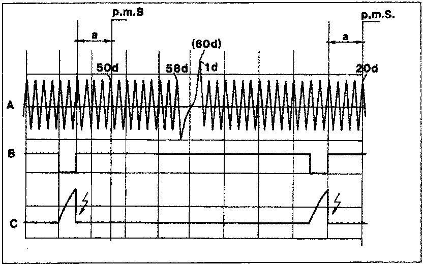
- A. Rpm sensor signal
- B. Power control
- C. Current circulating in the primary winding of a coil
- a. Ignition advance relating to the cylinder TDC
The interval or variation of the signal caused by the absence of 2 teeth on the phonic wheel, between the 58th and 1st teeth (also called synchronization tooth) which occurs for every rotation of the crankshaft pulley, is the reference signal which allows the electronic control unit to recognize an advance of 114° in relation to TDC of the pair of pistons 1-4 corresponding to the leading edge of the 20th tooth.
After acquiring the correct signal picture with reference to the TDC signal through the power module (internal) (5), the electronic control unit (see figure on next page) establishes the point of commencement of conduction (supply) of the primary circuits of the coils (6).
Parts & tools for this job For 1995 Fiat Bravo
- PARTFuel filterSearch: Fiat Bravo 1995 fuel filter
- TOOLFuel pressure test kitSearch: fuel pressure test kit
- TOOLFuel line disconnect toolSearch: fuel line disconnect tool
Links open Amazon search results in a new tab. As an Amazon Associate I earn from qualifying purchases.