
Wiring connectors
- Make
- Fiat
- Model
- Bravo /Brava (182) Factory Service Manual
- Year
- 1995–2001
- Section
- Fuel system (98 range, 1581 16v) › Wiring connectors
Wiring connectors
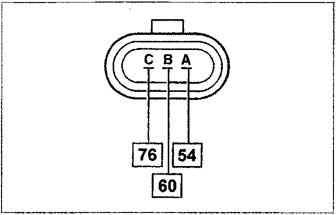
The numbers in squares indicate the corresponding control unit pins.
Pin A - Earth
Pin B – Positive
Pin C – Signal
Checking the resistance
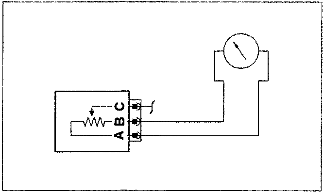
Sensor resistance may be measured as follows:
- connect an ohmmeter across sensor pins A and B and check a fixed resistance of 1200 ohms;
- check an ohmmeter between sensor pins A and C and check that resistance varies from 0 to 1200 ohm ± 20% when the throttle is moved.
Recovery
The system assumes a value calculated on the basis of rpm and pressure in the inlet manifold. If the pressure sensor fails at the same time, a throttle opening of about 50° is assumed as a fixed value.
Strategies to gradually decrease rpm at idle speed (dashpot) are blocked.
Idle speed self-adaption is blocked.
Mixture concentration self-adaption is blocked.
Removing-refitting
Procedure for premodification cars
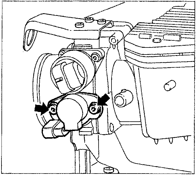
Disconnect the electrical connection, undo the two fixing bolts and remove the sensor.
NOTE The sensor is secured to the throttle body by two tabs with two non-slotted holes. Sensor angular position does not require adjustment because the control unit recognises throttle closed or fully open positions by means of special self-adaptive algorithms.
NOTE Whenever the potentiometer bolts are loosened or removed, they must be replaced because the threads are covered by a light layer of loctite. This secures the bolt once only.
NOTE On post-modification cars, the throttle valve position sensor is built into the throttle body.
Parts & tools for this job For 1995 Fiat Bravo
- TOOLDigital multimeterSearch: automotive digital multimeter
- PARTAssorted fuse kitSearch: car fuse assortment kit
- TOOLWire crimper and connector kitSearch: wire crimper connector kit
Links open Amazon search results in a new tab. As an Amazon Associate I earn from qualifying purchases.