
Wiring connector
- Make
- Fiat
- Model
- Bravo /Brava (182) Factory Service Manual
- Year
- 1995–2001
- Section
- Fuel system (98 range, 1581 16v) › Wiring connector
The fuel injectors are of the double jet "top-feed" type (with spray angled in relation to the injector axis). They are specific to engines with 4 valves per cylinder, and enable the jets to be directed towards the two inlet valves.
The jets of fuel at a differential pressure of 3 bar emerge from the injector, are instantly atomized and form two propagation cones.
The control logic of the injectors is of the "phased sequential type"; in other words the four injectors are driven in accordance with the intake sequence of the engine's cylinders, while delivery may start for each cylinder at the expansion stage up until the intake stage already started.
The injectors are fixed by the fuel manifold, which presses them into their seatings in the inlet pipes. They are also anchored to the fuel manifold by means of "safety stops". Two Viton rubber rings (1) and (2) ensure the seal on the inlet pipe and fuel pipe.
The fuel is supplied from the top (3) of the injector, whose body contains the winding (4) connected to the terminals (5) of the wiring connector (6).
NOTE During removal and refitting, do not apply stresses exceeding 120 N on the connector (6) of the injector in order not to impair its operation.
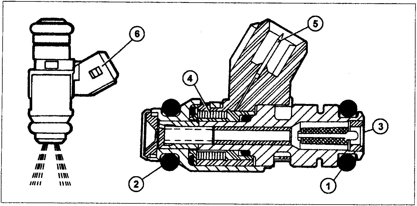
Wiring connector
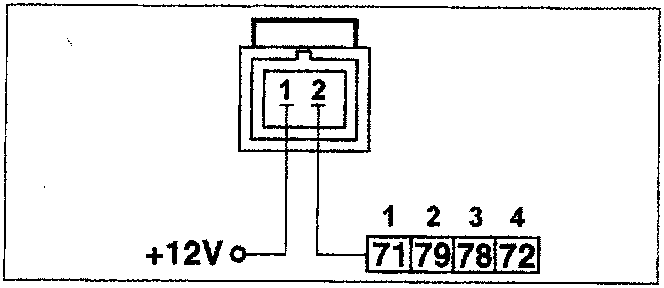
NOTE The numbers in boxes indicate the corresponding control unit pins positioned in the order of cylinder numbers.
Check the resistance
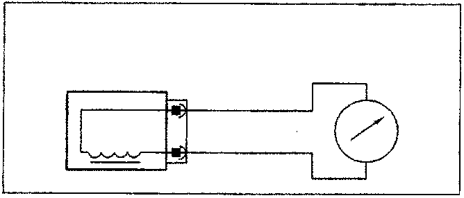
The injector's resistance can be measured by disconnecting the connector and connecting an ohmmeter as shown in the figure.
Resistance: 13.7 - 15.2 ohm at 20 °C
Parts & tools for this job For 1995 Fiat Bravo
- TOOLDigital multimeterSearch: automotive digital multimeter
- PARTAssorted fuse kitSearch: car fuse assortment kit
- TOOLWire crimper and connector kitSearch: wire crimper connector kit
Links open Amazon search results in a new tab. As an Amazon Associate I earn from qualifying purchases.