
R.r. front-end assembly
- Make
- Fiat
- Model
- Stilo Factory Service Manual
- Year
- 2001–2007
- Section
- Removing refitting › R.r. front-end assembly
R.R. FRONT-END ASSEMBLY
Removing
Place the car on a ramp.
- 5530B56 BATTERY DRIP TRAY COVER - R.R.
- 7055B54 under-engine guard - r r
Position a suitable container under the engine to collect the coolant.
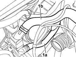
1. Disconnect the lower pipe (1a) and the upper pipe (1b) from the radiator.
To disconnect the pipe from the radiator, press the spring manually and release the rapid attachment for the pipe from the connector on the radiator.
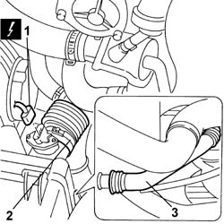
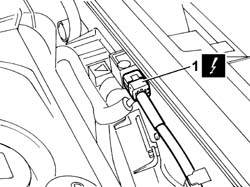
1. Disconnect the electrical connection from the air flow meter.
| Name | Connector | |
|---|---|---|
| 1 | Air flow meter | K41 |
2. Disconnect the turbocharger air inlet pipe.
3. Disconnect the air pipe from the resonator on the filter casing.
- 7055B42 Additional FRONT WHEEL ARCH (one), left or right - R.R. (Both sides)
- 4450B10 Front WHEEL (one) - R.R.
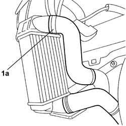
1. Disconnect the air pipes (1a) and (1b) from the heat exchanger.
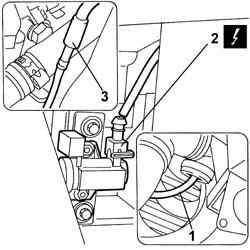
1. Disconnect the vacuum pipes for the variable geometry solenoid valve from the turbocharger.
2. Disconnect the electrical connection from the solenoid.
| Name | Connector | |
|---|---|---|
| 2 | Variable geometry turbine solenoid valve | L36 |
3. Disconnect the vacuum pipes for the variable geometry solenoid valve.
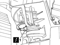
1. Disconnect the electrical connection for the horns.
| Name | Connector | |
|---|---|---|
| 1 | Horn | P5 |
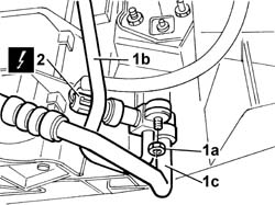
1. Undo the fixing nut (1a) and disconnect the air conditioning system pipes (1b) and (1c) from the lower coupling.
2. Disconnect the electrical connection for the linear sensor.
| Name | Connector | |
|---|---|---|
| 2 | Air-Bag front sensor | K39 |
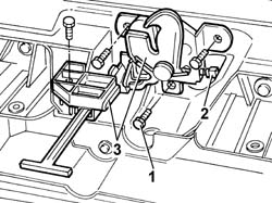
1. Unscrew the retaining bolts
2. Disconnect the bonnet release cable from the lock.
3. Remove the lock complete with opening device.
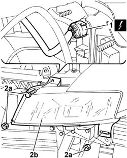
1. Disconnect the electrical connections for the front light clusters.
| Name | Connector | |
|---|---|---|
| 1 | Right headlamp | F11 |
| Name | Connector | |
|---|---|---|
| 1 | Left headlamp | F10 |
2. Loosen the nuts and the bolt (2a) fixing the front light clusters (2b) and move them towards the inside of the radiator.
1. Disconnect the electrical connection for the AIR BAG system first impact sensor secured to the fan.
| Name | Connector | |
|---|---|---|
| 1 | Air-Bag front sensor | K39 |
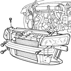
1. Undo the bolts fixing the reinforcement crossmember to the bodyshell struts.
2. Undo the bolts fixing the upper crossmember to the wings.
3. Remove the crossmember/light cluster/radiator assembly and fan.
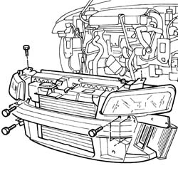
1. Undo the bolts fixing the reinforcement crossmember to the bodyshell struts.
2. Undo the bolts fixing the upper crossmember to the wings.
3. Remove the crossmember/light cluster/radiator and fan assembly (front end).
Refitting
Fit the crossmember/light cluster/radiator assembly and fan (front end).
Tighten the front end to the strut reinforcement crossmember to torque.
The bolts fixing the front end to the struts are tightened to a torque of 3 daNm.
Tighten the bolts fixing the front end to the upper crossmember.
Connect the electrical connection for the AIR BAG system first impact sensor secured to the fan.
| Name | Connector | |
|---|---|---|
| Air-Bag front sensor | K39 |
Place the two front lamps in the housing and tighten the fixing bolts.
Connect the electrical connections for the front light clusters.
| Name | Connector | |
|---|---|---|
| Right headlamp | F11 |
| Name | Connector | |
|---|---|---|
| Left headlamp | F10 |
Fit the lock complete with opening device.
Connect the bonnet release cable.
Tighten the bolts fixing the bonnet lock to the front end.
| Fastening | Component | Ø | Value (daNm) | |
|---|---|---|---|---|
| Bolt | BONNET LID LOCK/S | M6 | 0.8 |
Connect the electrical connection for the linear sensor.
| Name | Connector | |
|---|---|---|
| Air-Bag front sensor | K39 |
Connect the air conditioning system pipes to the lower coupling.
Connect the electrical connection for the horns.
| Name | Connector | |
|---|---|---|
| Horn | P5 |
Connect the vacuum pipes for the variable geometry solenoid valve.
Connect the solenoid electrical connection.
| Name | Connector | |
|---|---|---|
| Variable geometry turbine solenoid valve | L36 |
Connect the vacuum pipes for the variable geometry solenoid valve from the turbocharger.
Connect the air hoses to the heat exchanger.
- 4450B10 Front WHEEL (one) - R.R.
- 7055B42 Additional FRONT WHEEL ARCH (one), left or right - R.R. (Both sides)
- 7055B54 under-engine guard - r r
Connect the upper and lower engine coolant pipes.
Connect the air pipe to the resonator on the filter casing.
Connect the air inlet pipe to the turbocharger.
Connect the electrical connection for the air flow meter.
| Name | Connector | |
|---|---|---|
| Air flow meter | K41 |
- 7055B54 under-engine guard - r r
- 5530B56 BATTERY DRIP TRAY COVER - R.R.
- 0010T21 coolant check density and top up if necessary
- 0010T62 BRAKE and/or CLUTCH FLUID - Replace. fluid - Includes. washing pipes and bleeding air
Parts & tools for this job For 2001 Fiat Stilo
- TOOLTrim removal tool kitSearch: trim removal tool kit
- PARTTouch-up paintSearch: Fiat touch up paint
- PARTPanel clip assortmentSearch: Fiat panel clips assortment
Links open Amazon search results in a new tab. As an Amazon Associate I earn from qualifying purchases.