
Crankcase vapour/gas recirculation system
- Make
- Fiat
- Model
- Stilo Factory Service Manual
- Year
- 2001–2007
- Section
- Exhaust emission control system › Crankcase vapour/gas recirculation system
Crankcase vapour/gas recirculation system
The system controls crankcase emissions of vent gases consisting of mixtures of air, fuel vapours and burnt gases that leak through the piston rings and also lubricant oil vapours by redirecting them back to the engine so they can be burnt.
During engine operation, the oil vapours and the gases which escape through the piston seals into the crankcase are collected by a special system.
The system controls crankcase emissions of vent gases consisting of mixtures of air, fuel vapours and burnt gases that leak through the piston rings and also lubricant oil vapours by redirecting them back to the engine so they can be burnt.
OPERATION
During engine operation, the oil vapours coming from the crankcase are collected in the cylinder head.
Some of the oil vapours, condensed, drop back into the crankcase; the remaining vapours are sent to the intake through pipes (1) and (2).
At idle speed, the oil vapours flow through pipe (1), and at higher loads through pipe (2).
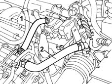
Operation
The oil vapour emissions are controlled by the pipe (4) which collects the vapours released from the crankcase and the rocker cover (1) which causes their partial condensation.
The uncondensed vapours are sent, through a pipe (5), to the turbocharger air inlet hose (3).
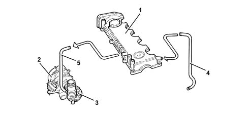
1 - Rocker cover
2 - Turbocharger
3 - Corrugated hose
4 - Oil vapour recovery pipe
5 - Oil vapour recirculation pipe
Function
The oil vapour emissions are controlled by a separator (1) which collects the vapours released from the crankcase (2) and from the tappet cover (3). The condensed vapours pass through a pipe (4) returning to the sump, whilst the uncondensed vapours pass through a pipe (5) and are sent to the turbocharger air intake hose.
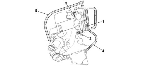
1 - Oil separator
2 - Crankcase oil vapour outlet
3 - Tappet cover oil vapour outlet
4 - Return to the sump of condensed vapours
5 - Intake vapour pipe
6 - Regulation valve
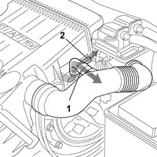
Blowby gases from the crankcase rise to the cylinder head and are conveyed to two different intakes:
- with medium-high accelerator throttle openings, the gases are taken in through the port immediately downstream from the air cleaner (1).
- with small throttle openings (particularly when the engine is idling or in over-run), gases are taken in downstream of the throttle (2).
OPERATION
Some of the oil vapours, condensed, drop back into the crankcase; the remaining vapours are sent to the intake through pipes (2) and (5).
At idle speed, the oil vapours flow through the pipe (5); at higher engine loads through the pipe (2). There is a spark out (1) inside the pipe (2) to prevent combustion due to flame returns from the butterfly casing (4).
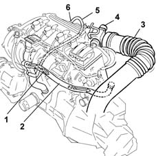
1, Spark out
2, Main exhaust gas recirculation pipe
3, Air filter - butterfly casing connecting hose
4, Butterfly casing
5, Idle speed exhaust gas recirculation pipe
6, Calibrated port
OPERATION
Blowby gases from the crankcase rise to the cylinder head and are conveyed to two different intakes:
- with medium-high accelerator throttle openings, the gases are taken in through the port immediately downstream from the air cleaner (detail A).
- with small butterfly openings (in particular with the engine idling or decelerating), the gases are drawn in by the PCV valve (Positive Crank Ventilation) fitted on the butterfly casing downstream of the actual butterfly (case B).
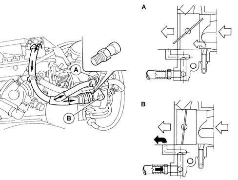
Operation
A regulating valve on the rocker cover, consisting of a spring (1) and diaphragm (2), prevents faulty intake phenomena.
When the vacuum values present under the rocker cover exceed a specified limit, the diaphragm moves downwards and blocks the pipe coming from the crankcase.
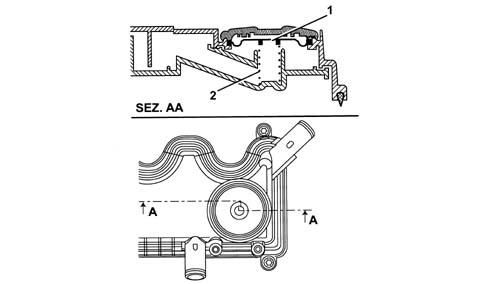
Function
There is a regulation valve (6) on the intake vapours pipe (5) with a spring that in normal conditions acts on a diaphragm keeping it open, thereby allowing the flow of oil vapours coming from the oil separator.
When the vacuum inside this pipe (5) exceeds the calibration, the spring moves the diaphragm closing the duct from the oil separator thereby preventing the intake of oil from the sump.
Parts & tools for this job For 2001 Fiat Stilo
- PARTExhaust gasketSearch: Fiat Stilo 2001 exhaust gasket
- TOOLPenetrating oilSearch: penetrating oil
- TOOLOBD2 scannerSearch: OBD2 scanner
Links open Amazon search results in a new tab. As an Amazon Associate I earn from qualifying purchases.